Download
1 / 21
220 likes | 374 Views
Moldflow Analysis Report CASE MF Report of pipe connector. ANALYSIS AIMS. To analysis original design, and check flow,cooling,and warpage. Plastic Material Introduction. PA66 Ultramid A3K : BASF The customer not supply the grade of material,we choose a general material.

E N D
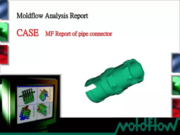
Moldflow Analysis Report CASE MF Report of pipeconnector
ANALYSIS AIMS • To analysis original design, and check flow,cooling,and warpage.
Plastic Material Introduction PA66 Ultramid A3K : BASF The customer not supply the grade of material,we choose a general material. 1. Melt Density 0.94627 g/cu.cm 2. Solid Density 1.1322 g /cu.cm 3. Ejection Temperature 180 deg.C 4. Recommended Mold Temperature 50 deg.C 5. Recommended Melt Temperature 290 deg.C 6. Absolute Max. Melt Temperature 300 deg.C 7. Melt Temperature Minimum 280.0 deg.C 8. Melt Temperature Maximum 300.0 deg.C 9. Mold Temperature Minimum 40.0 deg.C 10. Mold Temperature Maximum 60.0 deg.C 11. Maximum Shear Rate 60000.00 1/s 12. Maximum Shear Stress 0. 500 MPa PVT profile Viscosity model
Part Introduction The mostly wall thickness of part is imbalance shown by picture.
Feed System Design 1X4 cavities,two plate mold,Cold runner + Pin gate, the size is shown by picture.
Cooling system design Cooling system design is show by picture,the diameter of all channels is 6,8,10mm,the diameter of bubblers is 4-6mm.
Processing conditions Filling Conditions : Mold temperature : 50.00 deg.C Melt temperature : 290.00 deg.C Injection time 1.5sec Cooling Conditions: Coolant Temperature(Cavity) 40 deg.C Coolant Temperature(Core) 40 deg.C Packing Profile : P(MPa) Packing pressure at 80% Max. injection pressure 32.5 11.5 45.0 t(s) PRESSURE [MPa] STEP DURATION [sec] 32.5 0.0 32.5 10.0
Temperature (top),part Top temperature of part is balance shown by picture.
Temperature (bottom),part Bottom temperature of part is balance shown by picture.
Fill time Shown by picture is the filling status,flow is balance.
Temperature at flow front Temperature at flow front is balance shown by picture.
Air traps The magenta circles are possible air traps shown by picture,please attention venting.
Weld lines The black lines are possible weld lines.
Volumetric shrinkage Volumetric shrinkage is imbalance show by picture,please attention the setting of packing.
Injection Pressure & Clamp Force Max.: 6.8ton Max.: 40.7MPa Pressure at injection location Clamp Force
Deflection– X direction Deflection of X direction is balance, cause warp is little.
Deflection– Y direction Deflection of Y direction is balance,cause warp is little.
Deflection– Z direction Deflection– Z direction is balance, cause warp is little.
Summary • The results: • The flow status is balance, the injection and packing pressure are normal. • The volumetric shrinkage is imbalance,please attention the setting of packing. • The deflection of X&Y&Z direction is balance,cause warp is little;