Download
1 / 26
260 likes | 417 Views
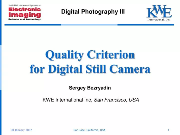
International, Inc. W. K. E. Digital Photography III. Quality Criterion for Digital Still Camera. Sergey Bezryadin KWE International Inc , San Francisco, USA. Introduction.

E N D
International, Inc. W K E Digital Photography III Quality Criterion for Digital Still Camera Sergey Bezryadin KWE International Inc, San Francisco, USA San Jose, California, USA
Introduction • Sensor spectral sensitivity plays the main role in color capturing accuracy. Luther-Ives condition formulated at the beginning of the last century determines requirements for camera’s spectral sensitivities necessary for correct color capturing. • For a three-detector camera, this condition may be formulated as follows: A color-capturing device with light detectors of three types may be used in correct color reproduction system if and only if a spectral sensitivity of every detector (DSS) in the system may be represented as a linear combination of Cone Fundamentals (CFs). • However, a century later, cameras available on the market still do not satisfy this condition. • There are many cases of incorrect color capturing due to disagreement between DSS and Luther-Ives condition. It may be most clearly illustrated by the following simple artificial example. San Jose, California, USA
Introduction • Consider the following two stimuli, consisting of two monochromatic components: • Stimulus 1 is perceived as a bright orange color : • 0.628 W with the wavelength λ=400 nm; • 0.848W with the wavelength λ=600 nm. • Its XYZ Tristimulus values are (905, 533, 43). • Stimulus 2 is perceived as a dark green color : • 0.233 W with the wavelength λ=500 nm; • 1.000W with the wavelength λ=700 nm. • Its XYZ Tristimulus values are (2, 79, 63). • However, the typical sensor depicted on the next slide produces the same RGB values for both stimuli. • So, for the sensor, colors corresponding to these stimuli are identical. San Jose, California, USA
DSSs of a typical CCD sensor • DSSs are displayed with bold solid lines, and their difference from DSSssatisfying the Luther-Ives condition are displayed with dotted lines. • Such a big difference between human perception and the sensor’s results is due to the fact that man’s sensitivity drops 100 times in a 600 to 700 nm range, while sensitivity of the red detector drops less than 2 times in the same range. San Jose, California, USA
Introduction In this presentation, • It is suggested to use an angle between detector sensor sensitivity and Cohen’s Fundamental Color Space as a criterion whether the particular detector may be used in a 3-detector system intended for accurate color capturing. • Also, this criterion may be used for color filter optimization in order to reach the highest color capturing accuracy available for a particular device. • Use of the criterion is illustrated with two types of digital camera sensors. • For more-than-three-detector set, it is suggested to use a value of the maximum angle between Cone Fundamentals and DSSs span as aSensor Quality Criterion. San Jose, California, USA
Fundamental Color Space (FCS) • In his 1953 doctoral thesis, Wyszecki suggested to represent a stimulus spectral distribution as a sum of two functions: s() = sf() + sr() (1) • sf() is a fundamental component; • sr() is a residual component. • Fundamental component is the same for all stimuli that have an identical influence upon a human. Tristimulus values of sf() are equal to Tristimulus values of the stimulus s(). • Residual component has no influence upon a human and its Tristimulus values are equal to zero. San Jose, California, USA
Fundamental Color Space (FCS) s() = sf() + sr() • The choice of the fundamental component involves some arbitrariness. • The arbitrariness may be significantly reduced if sf() is defined as an orthogonal projection of the stimulus s() onto a subspace spanned by Cone Fundamentals (CFs), so-called a Fundamental Color Space (FCS) introduced by Jozef Cohen in 1982. • With this restriction on the choice of the fundamental component, the corresponding residual component sr() is orthogonal to FCS. San Jose, California, USA
Fundamental Color Space II • Evolving Wyszecki and Cohen ideas, this formula s() = sf() + sr() may be applied not only to a stimulus, but also to a detector. • In this case, • s() is DSS; • sf() is an orthogonal projection of the DSS onto FCS; • An angle between the DSS s() and its orthogonal projection sf() is an angle between DSS and FCS. • Three-detector set satisfies Luther-Ives condition when this angle is equal to zero for each detector. • Thus, the angle between DSSs() and its orthogonalprojectionsf() may be used as a measure of DSS deviation and serves as a Quality Criterion for Digital Still Camera. San Jose, California, USA
Quality CriterionCalculation • Cohen’s method of orthogonal projection calculation is equivalent to the use of L2 metric. • With L2metric, the deviation angle may be calculated as follows: (10) • The orthogonal projection sf() may be calculated with DSS’s Tristimulus Values sf() = sxx*() + syy*() + szz*()(6) • where sx, sy, and sz areTristimulus Values of DSS s(); • functions x*(), y*(), and z*() are reciprocal basis in FCS. Their graphs are presented in the next slide. San Jose, California, USA
Reciprocal Basis for 10º XYZ CIE (1964) San Jose, California, USA
Reciprocal Basis Calculation • Functions x*(), y*(), and z*() for the reciprocal basis depicted in the previous slide may be calculated with the following matrix equation: (7) • where A is a constant dependent on the choice of wavelength units and ensuring this condition x*()x() d = y*()y() d = z*()z() d = 1 (8) San Jose, California, USA
Accuracy of Human Vision Model • To use the deviation angle φ as a quality criterion in light detector manufacturing, it should be determined what angle value may be considered as acceptably small. • Because the angle calculation is based on CMFs, this question is equivalent to a question about accuracy of human visual system model. • So far, all experiments on CMFs measuring provide slightly different results, and FCS based on 2º model is not the same as FCS based on 10º model. • One of the ways to estimate the accuracy of human visual system model is to determine a deviation angle φ between 2º CMFs and FCS, defined with 10º CIE (1964) data (or vice versa). San Jose, California, USA
Accuracy of Human Vision Model • This table represents deviation angles for 2° CMFs from 10° FCS. • The average deviation is about 5º, and it may be considered as a limit of accuracy provided by current Colorimetric concept. • Therefore, if the detector’s deviation angle φdoes not exceed 5º, the color capturing accuracy of the detector may be considered as perfect. • If the deviation angle φis more than 10º, such detector should be considered as unacceptable for a 3-detector system claiming accurate color capturing. San Jose, California, USA
Typical CCD Sensor • Deviation angles for discussed earlier typical CCD sensor are in the table. • As it was expected, angles are large. Especially, the for the red detector. • A good corrective filter may improve the sensor’s characteristics. Thus, a good traditional UV&IR filter, presented on the next slide, reduces the sensor’s average deviation angle 1.6 times. San Jose, California, USA
DSSs of a Typical CCD Sensor + UV & IR Filter • Thin lines represent the original DSSs. • The filter spectral characteristic is depicted in black. • Residual components for sensor with filter are displayed with dotted lines. • The residual components are still big in the middle of the range. San Jose, California, USA
Typical CCD Sensor + a Compound Filter • A compound filter with more complicated configuration, such as depicted in the next slide, for example, can cut down residual blue component, reducing the average deviation 1.5 times more than it could be done by the traditional filter. • But even with the theoretically best compound filter, the sensor average deviation is far beyond the 5º accuracy. • The main cause of the accuracy problem is an inappropriate choice of the red detector. San Jose, California, USA
DSSs of a Typical CCD Sensor + a Compound Filter • Thin lines represent the original DSSs. • The filter spectral characteristic is depicted in black. • Residual components for sensor with filter are displayed with dotted lines. • Until a short-wave boundary of the red detector is not shifted to the left with the sensitivity peak at 570 – 590 nm, the sensor cannot claim correct color capturing, whatever filter is used. San Jose, California, USA
DSSs of a Foveon sensor with an original filter • Foveon designs a sensor of a new type. • Curves of its DSSs with an original filter have an unusual shape and, at the first glance, good color capturing might not be expected from this sensor. • Residual components are displayed with dotted lines. San Jose, California, USA
New DETECTOR TYPE: Foveon • And indeed, its deviation angles are large. • However, with a proper compound filter, such as depicted in the next slide, for example, the situation remarkably changes: deviation angles become less than 5º. San Jose, California, USA
DSSs of a Foveon sensor with criterion-based filter • Thin lines represent the original DSSs. • The filter spectral characteristic is depicted in black. • Residual components for sensor with filter are displayed with dotted lines. • So, use of a filter similar to the one depicted here may lift a digital camera with Foveon’s sensor into a class of accurate color capturing devices. San Jose, California, USA
Sensors with more, than 3 Different Detectors • For a more-than-three-detector set, the Luther-Ives condition is a sufficient, but not a necessary requirement for correct color capturing. • So, in this case, a detector disagreement with the Luther-Ives condition is not a proof that the sensor can not be used for accurate color capturing. • The necessary and sufficient condition for an accurate color capturing with a more-than-three-detector set is less strong: DSSs span must include FCS as a subspace. • In this case, analysis should be done for the complete detector system, not for a particular single detector. • For more-than-three-detector set, a value of the maximal angle between Cone FundamentalsandDSSs span may be used as aSensor Quality Criterion. San Jose, California, USA
Set of 6 Different Detectors • For example, maximum deviation angle for a hypothetical six-detector set displayed here is 6.1º. San Jose, California, USA
Set of 6 Different Detectors • The difference between Cone Fundamentals and their orthogonal projection on DSSs span is displayed with a dotted line. San Jose, California, USA
Set of 8 Different Detectors • At the first glance, the difference between these 8-detector sets is insignificant, because they look very similar. • However, deviation angles for the upper set are less than 2º. fL = 1.0º fM = 1.2º fS = 1.7º • While deviation angles for the lower set are much bigger. fL = 4.0º fM = 4.9º fS = 15.8º San Jose, California, USA
Conclusion • As it may be seen from the last example, a simple increase in the number of detectors does not guarantee improvement of sensor’s color capturing quality. • While the more-than-three-detector-setversionis more general and valid for a three-detector-set too, • it can not be used for individual detector spectral sensitivity optimization; • it may be applied only to a whole set; • moreover, computation complexity is rising with increasing number of detectors. • So, use of a more-than-three-detector-set makes sense only if the cost of three-detector-set optimization is too high. • I believe, that the presented criterion may become a useful tool in digital camera manufacturing. San Jose, California, USA
Thank You! San Jose, California, USA