Download
1 / 14
150 likes | 298 Views
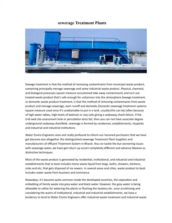
Treatment Plant Ozone Retrofit Program. California Unified Program 8 th Annual Training Conference February 8, 2006 Presented by: Paul G. Beswick Metropolitan Water District of Southern California Environmental Support Services (213) 217-5533 pbeswick@mwdh2o.com.

E N D
Treatment Plant Ozone Retrofit Program California Unified Program 8th Annual Training Conference February 8, 2006 Presented by: Paul G. Beswick Metropolitan Water District of Southern California Environmental Support Services (213) 217-5533 pbeswick@mwdh2o.com
California Aqueduct Colorado River Aqueduct Southern California’s Imported Water High Salinity Low DBPs Lower Salinity High DBPs SERVICE AREA
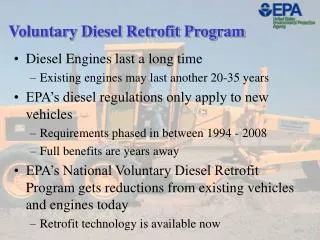
Drivers for Treatment Improvements • Water Quality • Regulatory compliance • Salinity management • Taste-and-odor control • System Operations • Remove plant capacity limitations • Maximize flexibility of supply
Poly Chlorine Alum/Ferric Acid Caustic Ammonia Chlorine Ammonia Caustic Plant Process Flow Diagram Ozone Destruct Ozone Oxygen Generation Ozone Generation Hydrogen Peroxide LOX Ozone Contactors Flash Mix Meter Filter Aid Floc Aid Chlorine To Member Agency Connection Finished Water Reservoir Flocculation Sedimentation Filtration
ORP General Design Criteria • Plant Flow Range is 60 to 750 MGD • Design Ozone Dose of 2.6 mg/L at 750 mgd • 8.6% Design Ozone Concentration • O3 Generation up 15,000 lb/day • Contactors Designed for 10 Minute HDT
Ozone Process Flow Diagram OZONE GENERATION SYSTEM OZONE CONTACTOR SYSTEM VENT OZONE DESTRUCT SYSTEM LIQUID OXYGEN FEED GAS SYSTEM PSU OZONE DESTRUCT CATALYST BED OZONE CONTACTOR OZONE GENERATOR DESTRUCT BLOWER LOX TANK LOX VAPORIZER HEATER OPERATING = 6 STANDBY = 0 FUTURE = 2 OPERATING = 2 STANDBY = 1 FUTURE = 1 OPERATING = 1 STANDBY = 1 DEFROST = 1 FUTURE = 1 OPERATING = 5 STANDBY = 1 FUTURE = 4 OPERATING = 2 STANDBY = 1 FUTURE = 1 OPERATING = 4 STANDBY = 1 FUTURE = 2 NITROGEN SYSTEM OPERATING = 1 STANDBY IS A BOTTLE SYSTEM RECEIVER TANK DRYER COMPRESSOR
Ozone Contactor Schematic Ozone Off Gas Raw Water Hydrogen Peroxide Ozone Feed Gas
Lessons Learned • Standardized Alarm Beacons • Disconnected Sample Line Vent to Contactor • Warning Signals on Ozone Building Roof • Safety Signs Throughout Facilities • Automatic Shutoffs in Boiler Room • New Gasket Material for Sulfuric Acid • New Gasket Material for Ozone System • Contactor Sample System Modification • Added check valve at O3 generator outlet • Seal Drain Sumps and Contactor Cover Plates • 1 Year Life on O3 Ambient Detector Probes