Download
1 / 41
410 likes | 564 Views
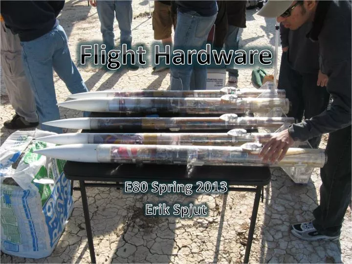
Flight Hardware. E80 Spring 2013 Erik Spjut. NASA Standards. Mechanical tests Strength Sinusoidal sweep vibration (5 to 50 hertz [Hz]) ELV and STS payloads Random vibration and acoustics Shock (mechanical and pyro) Modal survey Pressure profile Appendage deployment Thermal tests

E N D
Flight Hardware E80 Spring 2013 Erik Spjut
NASA Standards • Mechanical tests • Strength • Sinusoidal sweep vibration (5 to 50 hertz [Hz]) ELV and STS payloads • Random vibration and acoustics • Shock (mechanical and pyro) • Modal survey • Pressure profile • Appendage deployment • Thermal tests • Thermal/vacuum and ambient pressure thermal cycling • Thermal balance • Bakeout • Leak test for sealed components • EMI tests • Functional tests • Electrical interface • Comprehensive performance • Failure-free performance • End-to-end compatibility tests and mission simulations • Life test program • Mass properties verification
E80 Engineering Requirements • Payload Dimensions • Power Requirements • Acceleration, Shock, & Vibration • Temperature Profile • Speed of Response • Sensor Requirements • Construction Standards
Payload Dimensions • PC Board & Envelope • 1.80” by 10.10” (height depends on components) • Aerotech • ID 1.800” • Length Arreaux 12”, Barracuda 22.75”
Payload Dimensions • PC Board & Envelope • 1.80” by 10.10” (height depends on components) • PML – 12´´Payload Bay • Length 11.75” to 11.88” • ID Tube 2.152” • ID Coupler 2.02”
Power Requirements • Power Inputs • Data Logger: 6 V to 20 V • IMU: 5 V (regulated) & 3 V to 3.3 V (regulated) • AD623AN: 3 V to 12 V or ±1.5 V to ±6 V • MPC 60XX: 2.7 V to 6 V • Other sensors – TBD • Must measure current draw of final circuit. • Batteries must power for 1 hour minimum. • Turn on before launch, stay on during flight, turn off after recovery.
Power (cont) • Power sources • 9 V lithium, 750 mAh • 1.5 V • AAA Alkaline, 1000 mAh; Lithium, 1200 mAh • AA Alkaline, 2700 mAh; Lithium, 3000 mAh • 12 V (NEDEA- 1811A), 55 mAh • References • Duracell Tech Specs • Energizer Tech Specs
Power (cont) • Rechargable Batteries • LiPo (High Power Density, Special Charger, HazMat) • 3.7 V, up to 5000 mAh • 7.4 V, up to 5000 mAh • 11.1 V, up to 5000 mAh • NiMH • NiCd
Acceleration, Vibration, & Shock • Acceleration • From motor, 6 G to 50 G • Use RockSim or OpenRocket to estimate • Shock • From deployment charge, 2 G to 20 G • From parachute, 1 G to 50 G • From ballistic landing, 200 G +
Vibration • From motor • From aerodynamics • From shock impulse • Amplified at resonant frequencies • Viscoelastic damping materials
Temperature Profile • Standards • Commercial Grade: 0°C to 70°C • Industrial Grade: –40°C to 85°C • Military Grade: –55°C to 125°C • Launch • Often –2°C at 6 AM • Solar heating of payload section to 50°C+ • At standard lapse rate ∆T = –7.8°C @ 1200 m AGL
Sensor Requirement • Minimum 2 types of sensors • 2 Thermocouples wouldn’t count • 1 Thermocouple, 1 thermistor would (but see next) • Minimum 1 sensor with BW ≥ 1 kHz • Necessary speed of response • Mechanical Integrity (launch, flight, recovery) • Functional Placement
Speed of Response • Sensor adequate: • Needs deconvolution: • Hopeless:
Sensor Requirement (cont.) • Air Temperature • Sensor in free stream • Pressure Altimeter • No Flow • Pressure taps, 3 or 4 symmetric • Gas/Humidity Sensor • Gas flow to sensor
Pitot- Static Tube • Pitot Tube • In free stream • In direction of motion • Static Tap • Normal to flow • Preferable 4+ calibers from nose cone • Multiple in symmetric pattern best
Pitot Tube Designs http://naca.central.cranfield.ac.uk/reports/arc/rm/3365.pdf
Sensor Requirements (cont) • Light Sensor • Proper orientation • Proper view field • Vibration Sensor • Best on anti-node • Avoid node • Not for DC strain
Sensor Requirements (cont) • Particle/Dust Sensor • Gas flow through sensor • If optical, reduce or eliminate background reflections/light. • Often needs pulse train • Accelerometer/ Rate Gyroscope • Known fixed orientation • Means to deal with baseline and drift
Sensor Placement • Easiest in Payload Section • Next easiest in Nosecone • Ports/Channels to rout to exterior • Don’t forget separation for recovery • Can run (very long) wires through shock cord • Can make connector that separates at recovery • Can have separate sections
Video Camera • Battery charged by USB • 40 minute battery time on full charge • Creates 720P .mov file on microSD • 10 minutes per 1 GB. On 16 GB card will run out of battery before storage • Physical Mounting • Method • Location • Field of View
Data Logger • Created and programmed by Tyler Smelt • 16 channels • 16-bit resolution • Max 400 kSPS composite rate (25 kSPS/chan) • Max 200 kSPS on single channel
Data Logger • Power with 6 V to 20 V (9 V recommended) • Uses microSD for storage (have 16 GB cards) • Input range 0 to 3.3 V • Input Impedance ≈2.2kΩ • Set parameters with Config File • Have VI and .m file to read binary data files • PIC-32 microcontroller • 2 – AD7689 A/D
Single-Sided Circuits • Data logger expects 0 V to 3.3 V signals • Classical op-amp circuit power ±15 V • Low-voltage op-amp circuit power • ±1.4 V to ±3 V • 0-to-2.8 V to 0-to-6 V • Signal offset • Reference offset • Virtual ground
PC Board • Top laid out like your protoboard • 4 exterior buses slightly closer • 1 extra power bus • Bottom has connectors for data logger • 4 Holes for mounting • 2 holes for mounting battery holder
PC Board • Center has place for 5 V regulator + three more • Regulators can tie common to ground or not. • Bottom has connectors for data logger
Rocket Assignments • Team 1 – PML Phobos<.rkt> <.ork> • Team 2 – AerotechArreaux<.rkt> <.ork> • Team 3 – PML X-Calibur<.rkt> <.ork> • Team 4 – Aerotech Barracuda <.rkt> <.ork> • Team 5 – PML Phobos<.rkt> <.ork> If you feel you need a rocket different from the assigned, write a proposal explaining the technical reasons and give it to your section prof.
Rocket Construction • NAR or TRA safety Code is mandatory. • Materials:I will use only lightweight materials such as paper, wood, rubber, plastic, fiberglass, or when necessary ductile metal, for the construction of my rocket. • Motors:I will use only certified, commercially made rocket motors, and will not tamper with these motors or use them for any purposes except those recommended by the manufacturer. I will not allow smoking, open flames, nor heat sources within 25 feet of these motors.
Rocket Construction (cont.) • Adhesives must be used under fume hood, in spray-paint booth, or outdoors. • Neoprene gloves required. Eye protection recommended • G10 Fiberglass (PML fins) must be wet sanded or with full respiratory protection. Neoprene gloves strongly recommended. • No sharp implements permitted when removing plastic rivets.
Rocket Construction (cont.) • Spray painting only permitted in paint booth or outdoors. Skin & eye protection recommended. • If you follow the unmodified instructions for the rockets, you will not be able to fly them. • PML requires motor retainer, modified motor mount placement, and launch rail guides. • Aerotech requires motor retainer, longer motor mount, modified placement, and removal of motor hook, thrust ring, and thrust ring flange
Rocket Construction (cont.) • Motor retainers attached with JB Weld ONLY! • Epoxy (PML kits) • Surfaces to be joined must be pre-sanded with 80-to-120 grit sandpaper (and then de-dusted). • Mix small quantities at a time (exothermic reaction) • Epoxy flows until fully set • Epoxy clay • Not quite as strong as epoxy • Very useful for fillets and custom mounts • You always need less than you think
Rocket Construction (cont.) • Cyanoacrylic/Super-Glue (Aerotech) • Make SURE you have adequate ventilation • ALWAYS use skin protection (neoprene gloves) • Usually sets in 30 s to 20 min • Can use accelerator (we have limited supplies) • Accelerator on one surface + Super-Glue on other surface = instant bond when joined. • Will have to dribble on some internal joints
Rocket Hints • The PML Piston Strap is in the Piston parts.. • For PML kits, make sure fins are straight. • Use masking tape. • Use patience.
Rocket Hints (cont.) • For Aerotech kits, there is no need for the 24 mm motor adaptor. • For Aerotech kits, make sure the fins snap easily into the Fink Locks BEFORE putting the Motor Tube Assembly into the Body Tube. • For Aerotech kits, it’s very difficult to reconnect the shock cord to the nose cone. An extension from the screw eye to the end of the coupler makes the process much easier.
Payload Sections • PC board designed to fit in PML payload bay. • PC board matches Aerotech body tubing diameter. • A 14.75´´ long Aerotech body tube fits the PC board. • Arreaux payload section too short. • Barracuda payload section too long. • We have extras of both PML and Aerotech to allow for mistakes.
Deliverables • Week 1 • Scientific and/or Engineering objectives • Complete schematic • Parts list (especially to order) • Check off by Section Prof & Prof Spjut • Week 2 • Complete protoboard • Measured current draw • Demonstrate functionality • Check off by Section Prof & Prof Spjut
Deliverables (cont.) • Week 3 • Fully populated PC board • Demonstrate functionality • Check off by Section Prof & Prof Spjut • Week 4 • Completed Rocket • Complete ground and analysis procedures • Completed launch checklist (you have to DO steps) • Loaded launch motors
Deliverables (cont.) • Week 5 • List lessons learned • Fix & correct things • Load launch motors • Week 6 • Analyze data • Write Final Report • Prepare Final Presentation