Download
1 / 7
70 likes | 186 Views
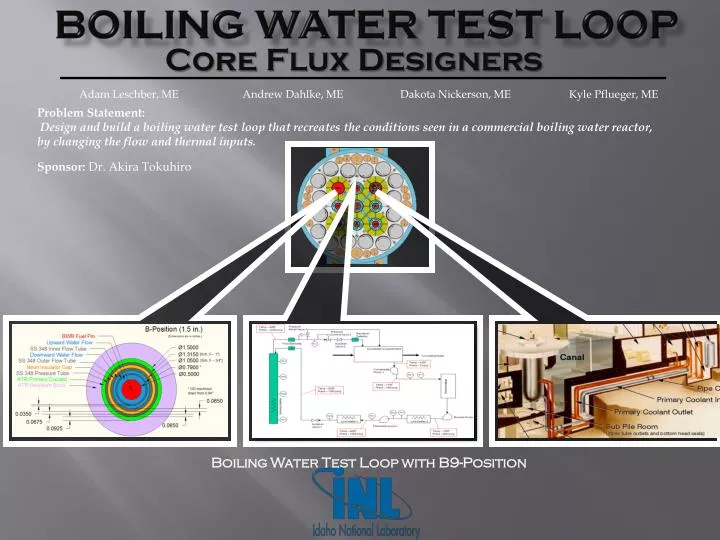
Adam Leschber , ME Andrew Dahlke , ME Dakota Nickerson, ME Kyle Pflueger , ME. Problem Statement:

E N D
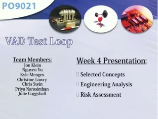
Adam Leschber, ME Andrew Dahlke, ME Dakota Nickerson, ME Kyle Pflueger, ME Problem Statement: Design and build a boiling water test loop that recreates the conditions seen in a commercial boiling water reactor, by changing the flow and thermal inputs. Boiling Water Test Loop Sponsor: Dr. Akira Tokuhiro Core Flux Designers Boiling Water Test Loop with B9-Position
Specifications: Piping and Control Specifications: Condensate Pump: AC motor driven centrifugal pump, self cooled Design Flow Rate – 25 gpm; Inlet pressure – 2 psig; Outlet pressure – 160 psig Booster Pump: AC motor driven centrifugal pump, self cooled Design Flow Rate – 25 gpm; Inlet pressure – 160 psig; Outlet pressure – 600 psig Feedwater Pump: AC motor driven centrifugal pump, self cooled Design Flow Rate – 25 gpm; Inlet pressure – 600 psig; Outlet pressure – 1100 psig Isolation Valve-1 Manually operated globe valve Size -TBD Isolation Valve-2 Manually operated globe valve Size -TBD Pressure Control Valve-1 Solenoid operated control valve Size -TBD Pressure Relief Valve-1 Spring loaded/self actuated Size -TBD Radiation Detector Ion Chamber Radiation Monitor TBD Demineralizer Bed Resin Size -TBD Quench Tank TBD Line heater-1 Electric inline heating element Voltage – TBD; Power – TBD; Inlet Temperature – 400F; Outlet Temperature – 530F Line heater-2 Electric inline heating element Voltage – TBD; Power – TBD; Inlet Temperature – 120F; Outlet Temperature – 400F In Tube Heater element Electric inline heating element Voltage – TBD; Power – TBD; Inlet Temperature – 530F; Outlet Temperature – 545F Flow Element-1 Venturi Tube Flow Element-2 Venturi Tube or Untrasonic Pressure Indicator-1 TBD Range - 2-200 psig Pressure Indicator-2 TBD Range - 100-800 psig Pressure Indicator-3 TBD Range - 100-1200 psig Pressure Indicator-4 TBD Range - 100-1200 psig Temperature Element-1 RTD Range - 80-150 F Temperature Element-2 RTD Range - 80-600 F Temperature Element-3 RTD Range - 80-600 F Temperature Element-4 RTD Range - 400-600 F Temperature Element-5 RTD Range - 400-600 F Temperature Element-6 RTD Range - 400-600 F Temperature Element-7 RTD Range - 400-600 F Pipe Stainless Steel Size -TBD • Reactor Specifications: • From BWTL Preliminary Analysis document, the reactor portion will be in the B position. This means that the following specs should be true. • From Final Presentation, the dimensions of the pipes in the tube are. Pressure tube, schedule 5-1”, Outer Flow tube schedule 5-0.75” and Inner flow tube schedule 5-0.5” with the OD machined to 0.79” and ID bored out to 0.72”. • Outer Section Inner Section Units • Density • 47.547.5 lbm/ft3 • Dynamic Viscosity • 6.4E-56.4E-5lbm/ft s • Flow Rate • 0.00148 0.00148 ft3/s • Flow Area • 0.00121 0.00146 ft2 • Hydraulic Diameter • 0.0183 0.0108 ft • Velocity • 1.011 1.220 ft/s • Reynolds # • 13754 9896