Download
1 / 1
10 likes | 239 Views
Figure 1. Figure 2. Figure 3. Figure 4. Brief Explanation of figure 1. Brief Explanation of figure 2. Brief Explanation of figure 3. Brief Explanation of figure 4. Programmable Resistive Load for High Voltage Power Supply Testing Arpan Ghosh, Michael Day {ghoshar, daym}@lexmark.com.

E N D
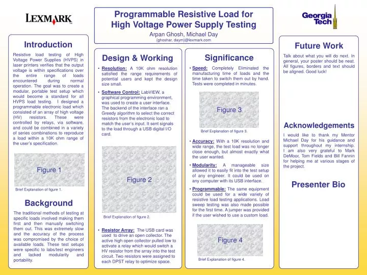
Figure 1 Figure 2 Figure 3 Figure 4 Brief Explanation of figure 1. Brief Explanation of figure 2. Brief Explanation of figure 3. Brief Explanation of figure 4. Programmable Resistive Load for High Voltage Power Supply Testing Arpan Ghosh, Michael Day {ghoshar, daym}@lexmark.com Introduction Resistive load testing of High Voltage Power Supplies (HVPS) in laser printers verifies that the output voltage is within specifications over the entire range of loads encountered during normal operation. The goal was to create a modular, portable test setup which would become a standard for all HVPS load testing. I designed a programmable electronic load which consisted of an array of high voltage (HV) resistors. These were controlled by relays, via software, and could be combined in a variety of series combinations to reproduce a load within a 10K ohm range of the user’s specification. Future Work Talk about what you will do next. In general, your poster should be neat. All figures, borders and text should be aligned. Good luck! • Significance • Speed: Completely Eliminated the manufacturing time of loads and the time taken to switch them out by hand. Tests were completed in minutes. • Accuracy:With a 10K resolution and wide range, the test load was no longer close enough, but almost exactly what the user wanted. • Modularity: A manageable size allowed it to easily fit into the test setup of any engineer. It could be used on any computer with its USB interface. • Programmable: The same equipment could be used for a wide variety of resistive load testing applications. Load sweep testing was also made possible for the first time. A jumper was provided if the user wished to use a custom load. • Design & Working • Resolution:A 10K ohm resolution satisfied the range requirements of potential users and kept the design size small. • Software Control:LabVIEW, a graphical programming environment, was used to create a user interface. The backend of the interface ran a Greedy algorithm to select the correct resistors from the electronic load to match the user’s input. It sent signals to the load through a USB digital I/O card. • Resistor Array:The USB card was used to drive an open collector. The active high open collector pulled low to activate a relay which would switch a HV resistor from the array into the test circuit. Two resistors were assigned to each DPST relay to optimize space. Acknowledgements I would like to thank my Mentor Michael Day for his guidance and support throughout my internship. I am also very grateful to Mark DeMoor, Tom Fields and Bill Fannin for helping me at various stages of the project. Presenter Bio Background The traditional methods of testing at specific loads involved making them first and then manually switching them out. This was extremely slow and the accuracy of the process was compromised by the choice of available loads. These test setups were specific to labs/test engineers and lacked modularity and portability.