Download
1 / 30
320 likes | 508 Views
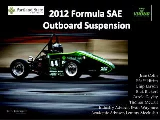
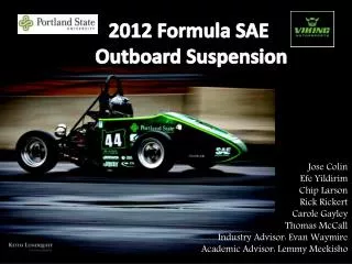
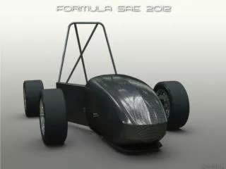
2012 Formula SAE Outboard Suspension. Jose Colin Efe Yildirim Chip Larson Rick Rickert Carole Gayley Thomas McCall Industry Advisor: Evan Waymire Academic Advisor: Lemmy Meekisho. Overview. Background Mission Statement Design Requirements Off the Shelf or Custom

E N D
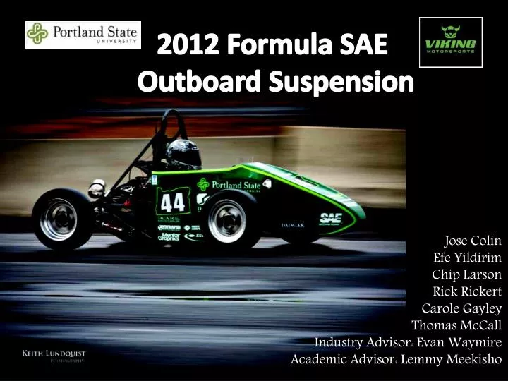
2012 Formula SAE Outboard Suspension Jose Colin EfeYildirim Chip Larson Rick Rickert Carole Gayley Thomas McCallIndustry Advisor: Evan Waymire Academic Advisor: LemmyMeekisho
Overview Background Mission Statement Design Requirements Off the Shelf or Custom Custom Design options Calculations Design Decision Final Design FEA Analysis Challenges and Solutions Conclusion
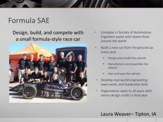
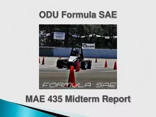
Background Each year, Viking Motorsport (VMS) designs builds and tests an open wheel racecar. FSAE OS Team will redesign the outboard suspension for MY12. 2012 Competition: June 20-23 in Lincoln, NE
Functional need for center-lock wheels Competition in Nebraska-it may rain at a moments notice, so wheel change would be quicker Less rotational inertia
Mission Statement FSAE-OS Team will design, validate and produce a new outboard suspension that will weigh less, have reduced part machining time and cost that integrates a centerlock system.
Design Requirements 2011 & 2012 parts are interchangeable Back-up system in case of failure Centerlock nut retention with two threads exposed FSAE rule Hub Weight Target: 2lb Must withstand 2G cornering load Customer requirement
Design Requirements • Ease of Manufacturing • Machining time: 80 min • Hub cost • $200 each • Service life • 2 years • Installation torque • No more than 300 ft.lbf
Off the Shelf Option • Centerlock • Oversized for FSAE racecar • Tripod CV joint • Cost prohibitive ($4000) Taylor Race FSAE/DSR hub and upright assembly
Custom Design • Large (~ 2”) Tapered Aluminum • Centers wheel • Expensive • Lower clamp force • Small (1/2” – 1”) Steel Hex • Inexpensive • Higher clamp force • Requires wheel centering method Wheel Nut
Custom Design • Castle Nut • Available in many sizes • Able to modify existing nut • Cuts reduce thread engagement • Poor pin resolution (60*) • Spindle Nut Retainer • Inexpensive • Readily available • 15* pin resolution • Difficult to produce custom units Wheel Nut Retention
2011 - Integrated brake hat • Increased machine time • Required larger OD material • 2012 - Separate brake hat • Plate steel • Machined in-house Custom Design 2011 Integrated Brake Hat 2012 Separate Brake Hat Brake Hat
2011 Wheel speed sensors taped to the uprights Custom tone rings were machined, threaded onto hubs 2012 Wheel speed sensors integrated into upright Custom Design Wheel Speed Sensor
Custom Design Upright Small changes: Retain 2011 geometry Reduce machine time Relocate wheel speed sensor Realigned caliper mounting
Hub • Wheel nut torque • Pin wheel contact stress • Wheel to hub friction • Thermal expansion • Bearings • Loads from cornering • Bearing to upright interference • Bearing hub interference Calculations
Design Decision Hub – Hardened Steel Integrated CV joint • Lighter • Retain 2011 axle Front and rear hubs identical • Reduce design/FEA time • Remove CV from front
Design Decision Upright – Aluminum • High strength • Ductile • Material: 6061-T6 Wheel Speed Sensor • Mounted inside upright • Reads slots in brake disc
Design Decision Separate brake hat, drive pins, wheel centering components and wheel retention Brake Hat • Cut from plate • Machined in-house • 4130 Steel • 3” OD stock for hub Drive Pins • 3 - ¼” drive pins • Off the shelf Wheel Retention • Aluminum spacer • Steel washer • M16x2.0 Class 12.9 nut • Spindle nut retainer R-ClipWheel Centering • Aluminum pilot
Final Design Analysis Front Hub Bending 2G cornering
Final Design Analysis Clamp force
Final Design Analysis • Uprightcamber compliance 2G cornering load Upper deflection: 0.063 mm Lower deflection: 0.152 mm Total deflection: 0.047* Camber compliance : 0.024*/G
Final Design Analysis Upright cornering
Final Design Analysis Upright braking
Final Design Analysis Brake hat, clamped
Final Design Analysis Brake hat , no clamp load
Challenges/Solutions High fatigue cycling in hub requires infinite life The hubs were designed using experimental fatigue data for similar materials and conservative assumptions No dynamic vehicle data Typical dynamic vehicle data from similar applications No budget Prototype parts were donated by Viking Motorsports, Warn Industries, ARE Manufacturing, Beaver Heat Treat, Dr. LemmyMeekisho and ZdenekZumr.
Challenges/Solutions Due to the necessity of donated manufacturing services, parts of a new design will not be ready to test and use on the car within the same year New designs tested and used on the next model year
Conclusion The Product Design Specification is the roadmap for the final design. Its completeness in satisfying known and unknown customer requirements is directly related to how good the final design is. Majority of time was spent working on non-design details