Download
1 / 41
410 likes | 514 Views
Official Use Only. Power Sensitive and Context Aware Global Positioning System. University of Utah Engineering Clinic 2009-10 September 3, 2009 Steven Paradise Adrian Wong Patrick Schindler. OFFICIAL USE ONLY

E N D
Official Use Only Power Sensitive and Context AwareGlobal Positioning System University of Utah Engineering Clinic 2009-10 September 3, 2009 Steven Paradise Adrian Wong Patrick Schindler OFFICIAL USE ONLY May be exempt from public release under the Freedom of Information Act (5 U.S.C. 522), exemption number and category: Department of Energy review required before public release. Name/Org Name: Adrian Wong / 8226 Date: September 4, 2008 Guidance (if applicable): Sandia is a multiprogram laboratory operated by Sandia Corporation, a Lockheed Martin Company,for the United States Department of Energy’s National Nuclear Security Administration under contract DE-AC04-94AL85000. Official Use Only
Official Use Only Overview • Project Motivation • Concept Study of Extreme Low Power Consumption Context Aware GPS Receiver with Software Processing • Areas of Study • RF hardware miniaturization and integration • Context aware power management for low consumption • Very short duration GPS snapshot acquisition • Incomplete GPS fragment navigation • Cross platform GNSS operation (GPS, Galileo) • Project Requirements • Target Platform: Sandia Stack Architecture • Time Constraint: March 25, 2010
Sandia Project Objective Fit a low power GPS receiver to a standardized Sandia stack form factor and log location. • Must run off CR2 batteries • Must log location for weeks • Must interconnect with stack
GPS Receivers ML-7 GPS Data Logger Cold Start Acquisition Time: 36 seconds Power Consumption: 5 V, 30 mA (150 mW) Trimble Copernicus GPS Receiver Cold Start Acquisition Time: 39 seconds Power Consumption: 3.3 V, 28 mA (92 mW) GR-10 / MN1010 GPS Receiver Cold Start Acquisition Time: 42 seconds Power Consumption: 1.8 V, 35 mA (63 mw)
Power Consumption • GR-10 GPS Receiver • Voltage 1.8 V • Current 35 mA • Power 63 mW • TTFF 42 secs • CR-2 Lithium Battery • Typical capacity of 800 mAh • System assumptions • Allow GPS 50% of system power • Take readings every 15 minutes • Zero power consumption when off • Operation Lifetime: 10 days • Energy Consumed: 3 J per sample • Continuous operation at 35 mA gives lifetime of 22 hours
Black Box Approach GPS Power LatitudeLongitude Altitude Antenna
1D Navigation • Measure the travel time from transmitter to receiver • Velocity of the signal is the speed of light • Distance = Velocity x Time • Small errors in Δt can cause large errors in distance
N + 1 for receiver clock offset • Second transmitter can correct for receiver clock offset • 1D problem: distance D is unknown, clock offset unknown • System of linear equations with two unknowns • 3D problem: three position unknowns + 1 time unknown • To calculate position in 3D, need a minimum of 4 receivers
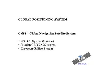
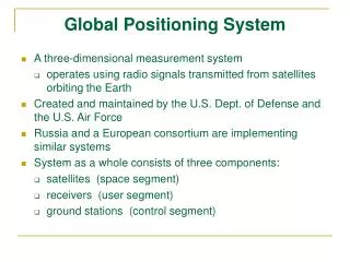
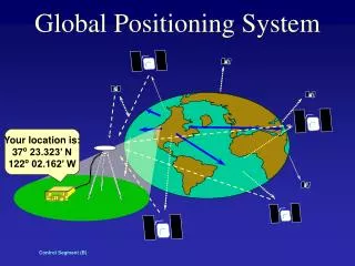
Satellite Navigation • Transmitters are now orbiting satellites with very accurate atomic clocks • Four satellites required • Latitude • Longitude • Altitude • Receiver clock offset
NAVSTAR GPS • NAVSTAR GPS by DoD • Up to 32 satellites in six orbital planes • Orbit at 20,000 km • 12 hour orbit
GPS Signal Structure • All transmit on the L1 frequency (1575.42 MHz) • CDMA (Code Division Multiple Access) • Modulated with Coarse/Acquisition PRN code • 1023 chips (each chip 1 us), repeats every 1 ms • Each satellite has a unique C/A code sequence • Data is BPSK at 50 bits per second
GPS Satellite Acquisition • PRN sequences are known to the receiver • Correlate the incoming signal with the 32 known PRN to find sat • Satellites flying around the Earth at 14,000 km/hr! • Introduces Doppler shift • Satellite acquisition is finding the GPS signal at the correct Doppler Shift and PRN Code Phase
Navigation Solution • System of linear equations with four unknowns
Remember This? GPS Power LatitudeLongitude Altitude Antenna
Current Solution RF Front End GPS Baseband RF Components LNA, IF mixer, ADC DSP Components Correlators, RTC GPS Components Navigation Solution LCD or PC Memory User Position Display Storage Data Logging
Official Use Only Overview • Project Motivation • Concept Study of Extreme Low Power Consumption Context Aware GPS Receiver with Software Processing • Areas of Study • RF hardware miniaturization and integration • Context aware power management for low consumption • Very short duration GPS snapshot acquisition • Incomplete GPS fragment navigation • Cross platform GNSS operation (GPS, Galileo) • Project Requirements • Target Platform: NESDAC Stack Architecture • Time Constraint: March 25, 2010
RF Hardware Miniaturization • “Software” GPS receiver • Correlations and navigation done on PC • RF signal amplified through LNA, mixed to IF, sampled with ADC • MAX2769 solution sends data through USB 2.0 to software running on a PC
Software GPS Solution RF Front End GPS Baseband PC Display RF Components LNA, IF mixer, ADC DSP and GPS Components Correlators, RTC, Nav User Position Display
Proposed GPS Solution GPS Baseband RF Front End Memory DSP and GPS Correlators, RTC, Nav RF Components LNA, IF mixer, ADC Storage Data Logging GPS Baseband PC Display DSP and Components Correlators, RTC, Nav User Position Display
Areas of Investigation • Reduce “GPS receiver” to RF front end • RHCP antennas • Capture samples only when necessary • Triggered by accelerometer movement, other sensors, or RTC • Capture and store GPS RF data to memory in very quick snapshots • Process incomplete GPS snapshot and integrate with known stored GPS ephemerides to calculate position
Project Status and Path Forward • Hardware prototype developed by last year’s team. • Revise the design and fabricate a new board • PCB design tools, steps from design through testing • Embedded programming • Architecting/writing code for on-board microcontroller • Take samples, store in memory, download to PC • Software design • Process GPS samples to determine board locations • Map samples to user interface on PC
Official Use Only Overview • Project Motivation • Concept Study of Extreme Low Power Consumption Context Aware GPS Receiver with Software Processing • Areas of Study • RF hardware miniaturization and integration • Context aware power management for low consumption • Very short duration GPS snapshot acquisition • Incomplete GPS fragment navigation • Cross platform GNSS operation (GPS, Galileo) • Project Requirements • Target Platform: Sandia Stack Architecture • Time Constraint: March 25, 2010
Estimated Dates • Project Kickoff (September 4) • Preliminary Design Review (September 29) • After Career Fair (3:30) • Critical Design Review (December 12) • Technical Open House (March 25) • Demonstration
Project Phases* • Phase I • Get acclimated with theory of GPS and hardware • Review results from last year • Develop project plan for the year Preliminary Design Review • Phase II • Revise/fabricate PCB for RF and digital components • Program microcontroller for power management, data storage, and USB interfaces • Calculate GPS navigation solutions Critical Design Review • Phase III • Integration, testing, and validation System Verification Review • Technical Open House
Preliminary Design Review* • Objectives • Propose and present the project • Convince audience of feasibility given constraints of time, effort, and materials • Demonstrate project has appropriate complexity • PDR should address the following • Outline of approach: block diagrams, ideas for architecture • Implementation of subsystems: how to realize • Division of labor, responsibilities, communication • Schedule: project milestones • Risks: areas of risk, mitigation plans • Should be able to answer questions like: • What does the system do? • What does it look like? • How will it be used?
Critical Design Review* • Objectives • Present the design of the system and how it will be implemented • Ideas should be concrete at this point, moving out of prototype stage (85%) • CDR should address the following • Block diagrams with functional description of parts and interfaces • Layout of circuit boards, parts, and mechanical interfaces • Complete specification of subsystems: circuit, logic diagrams, pinouts, interfaces with other systems • Test results and demonstrations of completed parts of the system • Parts list, bill of materials • Should be able to answer specific questions: • How much power does it consume? • How much space does it occupy? • How much does it cost?
Contact Information • Steven Paradise • sparadi@sandia.gov • 925.294.2755 • Patrick Schindler • pschind@sandia.gov • 925.294.2138
Where do we go from here? • Weekly status reports • Simple memos, don’t get bogged down in bureaucracy • Progress, decisions, what each person did • What you need from us • Define project and prepare for CDR • Open discussion with your group and with us • Minimum requirements: • Sandia stack form factor • Low power device • GPS logging
Interesting Links • http://gps.aau.dk/softgps/receiverTechnologyPart3.htm • http://www.sparkfun.com/commerce/categories.php?c=4 • http://www.cadsoft.de/ • http://www.pcb123.com/ • http://focus.ti.com/mcu/docs/mcugettingstarted.tsp?sectionId=97&familyId=4 • http://cegt201.bradley.edu/projects/proj2008/gps/Deliverables/Deliverables.htm • http://www.gps-sdr.com/
Possible Routes for RF Front End • SiGe GN3S Sampler V2 • Hardware highly integrated into USB stick (one on order, arriving soon) • MATLAB software package already available • Textbook available: A Software-Defined GPS and Galileo Receiver: A Single-Frequency Approach • Maxim MAX2769 Universal GPS Receiver • Development board in hand • Samples are easy to acquire • Gerber files and schematics available • Rakon GRM7520 • Miniaturized single channel GPS receiver • Built in LNA, SAW filter, IF filter, TCXO • May be difficult to acquire samples for testing
Suggestions for Microcontrollers • MSP430 known as a low power microcontroller • LPM3 uses barely any power • Toolchains are well established • Eclipse style IDE and debugger
Incomplete GPS Acquisition Approaches Recent research has moved toward GPS snapshots! • TIDGET (telemetry relay for missiles) • GeoTate (geotagging for cameras, hot-shoe drop-in) • A-GPS (ephemerides broadcast from cell network) • 10 mJ per capture Also, Galileo GNSS system is coming online soon.
Possible Route • For example, project flow could be something like: • Reverse engineering the SiGe USB stick • Source the SE4110 chip, design to Sandia PCB layout • Integrate MSP430 with on-board RTC and accelerometer to trigger GPS readings • Log data to Flash or EEPROM chip • Read out through USB with a USB UART (CP2102) • Modify the MATLAB source to retrieve SV ephemerides • Calculate recorded positions and display on map