Download
1 / 1
10 likes | 110 Views
Space side. 0.066” Al cover. 0.220” Al Stiffener. 0.2” thick Cu-W shield with Au-plate. 0.025” Au-plated lid. 0.091” thick ceramic chip carrier. PC board (0.0625”) with (2) 1-oz. copper planes (0.0014”) and 4 signal layers. Vehicle side. trapped electrons. trapped electrons.

E N D
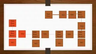
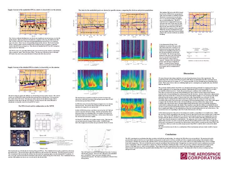
Space side 0.066” Al cover 0.220” Al Stiffener 0.2” thick Cu-W shield with Au-plate 0.025” Au-plated lid 0.091” thick ceramic chip carrier PC board (0.0625”) with (2) 1-oz. copper planes (0.0014”) and 4 signal layers Vehicle side trapped electrons trapped electrons trapped electrons trapped electrons trapped electrons trapped protons trapped protons trapped protons trapped protons trapped protons Supply Current of the unshielded FPGAs relative to dose/orbit over the mission The data for the unshielded parts are shown for specific storms, comparing the electron and proton populations The Antifuse TID test on the FPGA board involved an A1280A device programmed with a known number of antifuses burned. The device was powered at an elevated VCC to encourage breaking of antifuses due to total ionizing dose. The DUT experienced an exaggerated increase in current at the onset of the Aug. 28, 1998 electron event. It was first assumed that this was the end of the device but after a while, the device appears to have annealed. While the current consumption has gone up since launch, there have been no telltale jumps in the current to indicate an antifuse breaking. The 3 devices without shielding have not shown any significant current increase over the life of the mission. However, the traces do indicate a response to the Aug. 28, 1998 storm (Rev. 590). In May, 1999, DUT 2 (the space-facing unshielded part powered at 3.3V) began to spew out errors. There was no corresponding change in the current. The board was shut off for a while to figure out the problem and to change the turn on sequence so that the clock to that DUT was no longer on. This effectively disabled the DUT for SEU testing but kept it active for TID study. All 3 DUTs seem to be annealing following the powered-down period, which is coincidental with a relatively “quiet” time in terms of dose. The dose per orbit shown here is through 49.9 mils of Al, close to the actual 66 mils of Al that is the lid to the test bed. A one-dimensional Monte Carlo simulation was made of the space-side and vehicle-side parts' response to an incident electron spectrum, with and without extra shielding in the form of the 220-mil Al stiffener and 200-mil Cu-W shield. The electron spectrum incident on the space side of the 66 mil Al cover was derived from the AE8-MAX model for a spacecraft in a "generic" Molniya orbit with 600 km perigee and 345 degree longitude of apogee. Combined energy deposits (direct electrons plus bremsstrahlung) were logged, and are summarized in Table II. Supply Current of the shielded FPGAs relative to dose/orbit over the mission Discussions Of course the most interesting result does not come from the primary focus of the experiments. The monitoring of the currents on the FPGA board for TID effects was included in the SEU experiment in an effort to get the most out of a single 4.5” x 6” board as possible. It is here though that the surprising fact is found. That is, the 2 devices that are exhibiting higher power consumption are significantly more shielded than the other DUTs. The particular shields added to the DUTs were designed and tested specifically for stopping proton dose in another application. It was hoped that the shields would help the FPGAs last long enough to see an SEU, provided the testbed stayed on. Clearly the proton data gave confidence that would be the case. Since there is an increase in current in the shielded parts only, it must be from an interaction with the material such as bremsstrahlung dose enhancement from the electrons, electron collision dose enhancement, higher dose from protons due to energy loss in transport through the shield, or even activation of the shield material from the protons (copper is a known bad actor with a long half-life once activated). To help determine what is causing the dose enhancement, the changes in the rate of increase in the curve was correlated with actual events in the space environment. Electrons dominated these events. This would appear to support the idea that the effect is due to bremsstrahlung or electron collision dose enhancement. Looking at the expected dose due to bremsstrahlung using AE8 models, it does not look like enough dose could really be making through to the shields. These numbers argue that the stiffener and shield effectively cut down on dose in parts beneath them both for direct electrons and for bremsstrahlung. The direct electron dose is significantly higher for the unshielded part than the bremsstrahlung dose for any of the devices. The current increases are responding to only 10s of rads of electrons in a few days. As the mission progresses, the parts are becoming more sensitive, responding to even smaller doses. While the current is clearly responding to the electrons, it may be that it has become more sensitive due to TID from protons. That is, the CuW shields may be so effective in slowing the protons (even stopping them at some energies) that the effective total dose is much greater. The result would be that these particular parts are “aged” more than the dosimeters would indicate. The aging may also be due to additional dose from the shield being activated. In order to activate the material, the incoming particle needs to have enough energy. In the space environment, it is generally true that protons, which can have energies greater than 10MeV, but not electrons, which are rarely seen with energies greater than 8MeV, would be able to activate the shield material. The effects seen here may be due to a combination of these mechanisms and more study would be of great benefit. The devices that are under the stiffener are all showing increases in the current. The control Actel is an A1280A FPGA that reads the data and interfaces with the host. It is located on the vehicle side of the board. The dose per orbit is shown for the thickest dome of the 3 dosimeters on the spacecraft, the 125.5-mil Al. It is the closest to the actual 286 mils of aluminum covering the control Actel and DUTs 3 and 4. The data has been expanded around two periods of storms and shown here with data on protons with energies greater than 15 MeV and electrons greater than 2.9 MeV. In 1998, the series of storms that began in August were very intense electron storms. The proton data for this period also shows the injection of a temporary new proton belt. In July of 2000, the proton event that occurred on the 14-15 did not seem to cause the current to change. Instead, in September when the proton belts were subsiding, there was another storm that was much more intense in terms of electrons. At the onset of this storm the currents increased more rapidly. On March 31, 2001 there was another intense storm. This time the current had started to change 10 days earlier. SAMPEX data shows the trapped electrons that also preceded the March 31 storm. The FPGA board and its configuration on the MPTB Conclusions The SEU experiments are producing data that correlates well with the ground testing. In contrast, the TID effects were not predicted. The unexpected results presented here indicate that the use of spot shields on integrated circuits needs to be done carefully and with a complete understanding of the intended orbital environment. Whether the protons in the radiation belts or electrons during storms are the cause, the second caution is in understanding when a device is failing from total ionizing dose. The rate at which the part is exposed can influence the total dose limit. Enough dose in a short period to cause a sudden increase in the power consumption, with not enough time to anneal out, will give the illusion of hitting the limit. In fact, the part may continue to function much longer in the absence of the high rates (i.e., after a storm subsides). These important observations point to the necessity for more flight experiment suites for continued improvement of ground testing and expanded understanding of how to get reliable electronics into space. The final point is that it is always exciting to get the unexpected result. The board made use of both sides for the large flat-pack FPGAs. The 2 shielded devices made a sandwich as shown in the sketch above. The test bed had to add some stiffeners to the boards to fix vibrations. The FPGA board is in slot 3. The orientation of the board and the stiffener has the metal bar spanning right across the shielded DUT sandwich. It also covers the control Actel which is mounted on the inward, vehicle-facing side of the board. The 3 unshielded devices and the 1280 antifuse test device are covered only by the 66 mil Al lid. The CuW shield was tested at the Indiana University Cyclotron with 46 MeV protons. Data was also collected on an unshielded part, a RADPAK™ part, and a part shielded with an experimental material. The data is normalized to 1Mrad of dose from protons.