Download
1 / 26
260 likes | 381 Views
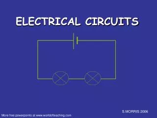
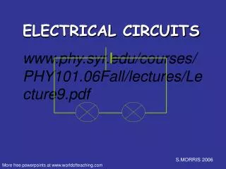
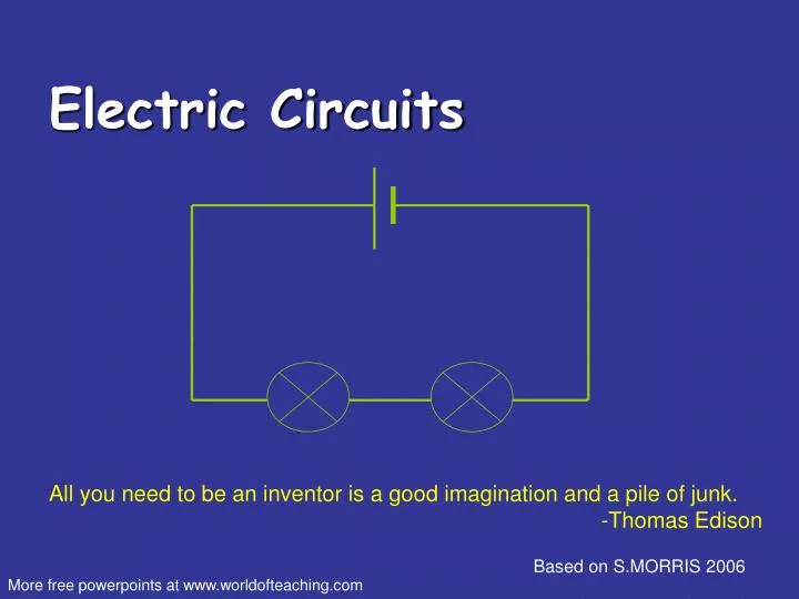
Electric Circuits. All you need to be an inventor is a good imagination and a pile of junk. -Thomas Edison. Based on S.MORRIS 2006. More free powerpoints at www.worldofteaching.com. Electricity – electrons moving through a metal wire. The CELL.

E N D
Electric Circuits All you need to be an inventor is a good imagination and a pile of junk. -Thomas Edison Based on S.MORRIS 2006 More free powerpoints at www.worldofteaching.com
The CELL The cell stores chemical energy and transfers it to electrical energy when a circuit is connected. An example of a cell is a Battery. The cell’s chemical energy is used up pushing a current around a circuit.
What is an electric current? An electric current is a flow of microscopic particles called electrons flowing through wires and components. - + In which direction does the current flow? By convention (thanks to Ben Franklin) - from the Negative terminal to the Positive terminal of a cell. (Electrons actually move in the opposite direction, from the negative terminal to the positive one.)
Switch 1 Switch 2 Lamp 1 Lamp 2
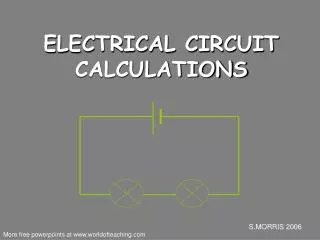
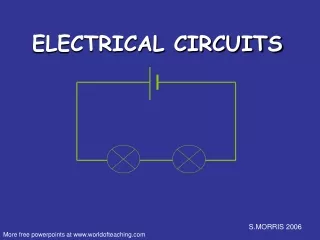
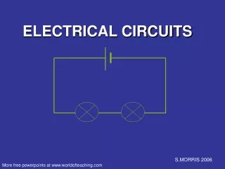
simple circuits Here is a simple electric circuit. It has a cell, a lamp and a switch. wires cell lamp switch To make the circuit, these components are connected together with metal connecting wires.
simple circuits When the switch is closed, the lamp lights up. This is because there is a continuous path of metal for the electric current to flow around. If there were any breaks in the circuit, the current could not flow.
circuit safety • If you connect a wire between the two terminals, the electrons will flow from the negative end to the positive end as fast as they can. This will quickly wear out the battery and can also be dangerous • To properly harness the electric charge produced by a battery, you must connect it to a load. The load might be something like a light bulb, a motor, a resistor or an electronic circuit like a radio.
circuit diagrams In circuit diagrams components are represented by the following symbols; generic resistor cell or battery switch lamp buzzer voltmeter resistor variable resistor ammeter motor
circuit diagram Scientists usually draw electric circuits using symbols; cell lamp switch wires
Ohm’s Law I = V / R I = Current (Amperes) (amps) V = Voltage (Volts) R = Resistance (ohms) Georg Simon Ohm (1787-1854)
How you should be thinking about electric circuits: Voltage: a force that pushes the current through the circuit (in this picture it would be equivalent to gravity)
How you should be thinking about electric circuits: Resistance: friction that impedes flow of current through the circuit (rocks in the river)
How you should be thinking about electric circuits: Current: the actual “substance” that is flowing through the wires of the circuit (electrons!)
measuring current Electric current is measured in amps(A) using an ammeter connected in series in the circuit. A
measuring current This is how we draw an ammeter in a circuit. A A PARALLEL CIRCUIT SERIES CIRCUIT
measuring current SERIES CIRCUIT 2A • current is the same • at all points in the • circuit. 2A 2A PARALLEL CIRCUIT 2A 2A • current is shared • between the • components 1A 1A
copy the following circuits and fill in the missing ammeter readings. ? 3A 3A ? 4A ? 1A ? 4A 4A 1A ? 1A
measuring voltage The ‘electrical push’ which the cell gives to the current is called the voltage. It is measured in volts (V) on a voltmeter V
measuring voltage Different cells produce different voltages. The bigger the voltage supplied by the cell, the bigger the current. Unlike an ammeter a voltmeter is connected across the components Scientist usually use the term Potential Difference (pd) when they talk about voltage.
measuring voltage This is how we draw a voltmeter in a circuit. V V SERIES CIRCUIT PARALLEL CIRCUIT