Download
1 / 11
110 likes | 230 Views
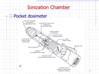
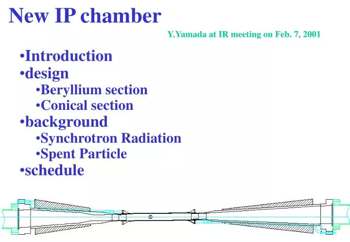
New IP chamber. Y.Yamada at IR meeting on Feb. 7, 2001. Introduction design Beryllium section Conical section background Synchrotron Radiation Spent Particle schedule. Introduction. Purpose better impact parameter resolution : s R SVD first layer

E N D
New IP chamber Y.Yamada at IR meeting on Feb. 7, 2001 • Introduction • design • Beryllium section • Conical section • background • Synchrotron Radiation • Spent Particle • schedule
Introduction • Purpose • better impact parameter resolution : s RSVD first layer • s = 30 mmforRSVD first layer = 30 mm (SVD1) • s = 21 mmforRSVD first layer = 21 mm (SVD2 Rbp=15 mm) • s = 15 mmforRSVD first layer = 15 mm (SVD2 Rbp=10 mm)
Modification from SVD1 • Rinner : 20 mm 10 mm or 15 mm • Beryllium section tilted : 0 mrad 11 mrad • Cooling for Be section : He PF200 (liquid) • Cooling for cone section : grooves brazed tubes • Material for cone section : Aluminum Tantalum • More Tungsten masks • Total weight : 8 kg 35 kg (under study) • Schedule • to be installed summer 2002
Design • 1. Beryllium section • double wall of Be (Inner:0.5 mmt, Outer:0.25 mmt) cylinder • tilted by 11 mrad from Belle/LER axis and HER axis • Inner surface coated by 10 mm thick sputtered gold • cooled by PF200(liquid) in 0.5 mm gap between Be pipes • Brazed with SR mask parts made of SUS
1.1 Cooling of Be section • Heat source • Synchrotron light : < 10 W • Image current : 25 W • HOM : < 100 W • Coolant : PF200 (water) • density(g/cm3) : 0.78 (1.0) • viscosity(g/cm/s) : 0.019 (0.010) • Thermal cond. (W/m/K) : 0.16 (0.62) • Specific heat (J/g/K) : 2.3 (4.2) • Cooling property • Flow rate : 25 cm3/s (80cm/s, Re=328, DP=0.14kg/cm2) • DT(liq.) = 2.2 ºC, DT(bulk-wall) = 4.9 ºC
2. Conical section • Vacuum chamber made by Tantalum(Z=73) • Saw tooth inner shape to avoid SR scattering into Be section • Inner surface coated by 10 mm thick sputtered gold • Cooled by water tubes brazed outside Ta chamber • Surrounded by Heavy Metal (W:95%) masks • Brazed SUS ring to be welded with SUS of Be section • SUS flange which has same shape with SVD1
Background • 1. Synchrotron Radiation • 1.1 Source of SR • Soft SR from HR upstream : mainly BC3LE, QC2LE, QC1LE • Hard (38keV) SR by QCSR and backscattered from QC2RE chamber
1.2 SR simulation • Simulated by SRGEN + EGS4 • Sources which damaged SVD1.0 : • BC3LE(300krad/10days) + QC2LE(50krad/10days) + QC1LE(500krad/10days) • Design for SVD2 • 1. Tilt 11 mrad w.r.t. Belle/LER axis and HER axis • 2. Complete sawteeth shape on HER side ( ~1/50 dose reduction) • 3. 3mm SUS Masks away from IP + 250 mm gold foil (~1/10 dose reduction) • 4. Tantalum vacuum chamber which absorbs 38 keV SR • Results of simulation • dose by soft SR from HER upstream : 0.01krad/yr • dose by hard SR from QC2RE : negligible small • dose by SR from LER : negligible small • SR during injection : avoid >3mm offsets in x or y at QC1 and QC2
2. Spent particle • Source of Spent Particle Background • 1. Bremsstrahlung in HER/LER • 2. Coulomb scattering in HER/LER • 3. Touscheck effect in LER (not simulated) • Simulation of Spent Particle Background • TURTLE for whole ring (incl. masks) GEANT from QC2 to BELLE • Comparison Data and simulation for SVD1 first layer • Condition : 2.6A+1.1A, 1 nTorr • Data : HER 24 kRad/yr, LER 82 kRad/yr • Simulation : 49 krad/yr • HER : 9 kRad/yr (Brem. : 5 + Coul. : 4 ) • LER : 40 kRad/yr (Brem. : 5 + Coul. : 35 ) • agreement is within factor of 2 ~ 3
Simulation on SVD2 total 124 kRad/yr total 106 kRad/yr increase by factor 2 ~ 3 from SVD1 : tolerable?
Schedule • Design fixed by Mar. 31st, 2001 • Fabricated by Mar. 31st, 2002 • Assembled with SVD2 in Apr. 2002 • Installed into Belle in Aug. 2002