Download
1 / 27
280 likes | 507 Views
Computer Methods and Systems, 21-23.XI.2007, Krakow. Detection of anisotropy of friction surface images. Zbigniew Rudnicki, dr inż . , Marek Mruk, mgr. Introduction. Processes of friction and corresponding wear very often cause: changes of surface anisotropy .

E N D
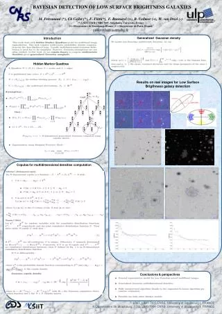
Computer Methods and Systems, 21-23.XI.2007, Krakow Detection of anisotropy of friction surface images Zbigniew Rudnicki, dr inż., Marek Mruk, mgr
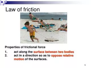
Introduction • Processes of friction and corresponding wear very often cause: changes of surface anisotropy. • The paper describes application of computer image analysis for friction surface state inspection by: - measuring of surface image anisotropy
Changes of surface anisotropy The wear process can cause: • increase of anisotropy or • decrease of anisotropy depending on initial state of surface.
Example 2. Increase of anisotropy- caused by wear of cross-hatch finished surface of Perkins tractor machine cylinder
The Goal of research Verification of usability of some image features- which are often used in gray texture image analysis - for measuring of the anisotropy and directionalityin friction surface images
Anisotropy of image feature. Definitions: • The investigated feature C possessesan anisotropy when the values of this feature depends relevantly on the scanning angle q (or image rotation angle -): C(q) const • The anisotropy measureAn(C) of the feature C(q) is defined as: An(C) = 1 - min(C(q)) / max(C(q))
The main direction of image feature • If the function C(q) has the global maximum for angle q1 so this angle designates the main direction of this feature and the image possesses directionality on account of the feature C • If more than one local maximum of C(q) is significant - so more than one direction can be taken into consideration.
The main steps of the research: A) Investigation of selected image featureson the base of several pattern images,for working out the best method of detection and measuringof anisotropy and directionality B) Measuring of anisotropy and directionality for some classes of real images- as the test of proposed method.
Subtopics in step A: • Selecting the feature which is the most sensitive on image anisotropy • Defining: the measure of image anisotropy for selected feature, and the main direction of image • Feature standarization to range [0; 1] and to make independence on image size • Working out computer programs for: • Inspection (by graphs) of feature dependence on skanning angle • Measurement of anisotropy • Measurement or main direction and the second direction (if exists)
Skanning angle and rotation of images The skanning angle was: q = 0o for all features which were extracted. For evaluation C(q) - instead of changing q,the sequence of image rotations by angle was applied: = 0o, -5 o, -10 o, ..., -180o. So the result was the same as for:q = - = 0o, 5 o, 10 o, ..., 180o
Features from: “Run Length Matrix” R All investigated features were calculated from:Run Length Matrix: RMatrix Ris obtained for given scanning angle q The value of matrix element Rg,j gives information: - how many “runs” of length j and gray level gthere were in the image. The size of matrix R are Lg x Lrwhere: Lr - maximal length of run (in pixels)Lg - number of gray levels.
The features calculating from matrix R: (1) Short Run Emphasis inverse moment„Odwrotny moment uwydatnienia krótkich pasm” (2) Long Run Emphasis moment“Moment uwydatnienia długich pasm” (3) Run Length Nonuniformity“Niejednorodność pasm” (4) Fraction of image in runs„Część obrazu w pasmach”
The features calculating from matrix R: (1) (2) (3) (4) where: Lk = number of columns in image (or pixels in row), N = number of all pixels,
Feature standarization - to range [0;1](gives independence on image size) Only the features LngRemph and RLNonUni need standarization : (2a) (3a)
Redefinition of investigated features Only the feature LRE has maximum for main direction of texture and other features has minimum for this direction so they was redefined. Finally - the four investigated features were: C1()= 1-SRE(), C2() = LRE(), C3() = 1-RLN(), C4() = 1-FIR().
The results for pattern image 1: 255 gray levels
The results for pattern image 2: Only 3 gray levels:0, 120, 240
The results for pattern image 3: Beforecorrection Aftercorrection
The results for real images (1): „New” „Wear”
Image feature LRE anisotropyfor 2 classes of images (2)surfaces of Perkins machine cylinders:
LRE discrimination ability - Fisher’s coefficient: Where: - mean V - variance
Summary • The feature: Long Run Emphasis Moment was standarized - as LRE - and selected as the best feature for measurement of image anisotropy • The measure of anisotropy on the basis of this feature was defined • Many computer programs in Matlab were worked out for analysis of anisotropy (as function of scanning angle) and evaluation of image directionality • These programs were applied with success not only for pattern images but to some classes of real images too.