Download
1 / 17
240 likes | 904 Views
OVER VOLTAGE OR UNDER VOLTAGE ALERT SYSTEM. Introduction. The aim of the project is to make a low voltage and high voltage indicator . This system will save costly electrical and electronic appliances from the adverse effects of very high and very low mains voltages.

E N D
OVER VOLTAGE OR UNDER VOLTAGE ALERT SYSTEM
Introduction The aim of the project is to make a low voltage and high voltage indicator. This system will save costly electrical and electronic appliances from the adverse effects of very high and very low mains voltages. The circuit features auto reset and utilizes easily available components. It makes use of the comparators available inside 555 timer ICs. Supply is tapped from different points of the power supply circuit for the display and control circuit operation to achieve reliability.
EMBEDDED SYSTEMS Definition for :- EMBEDDED SYSTEMS • A combination of hardware and software which together form a component of a larger machine. • An example of an embedded system is a microprocessor that controls an automobile engine. • An embedded system is designed to run on its own without human intervention, and may be required to respond to events in real time.
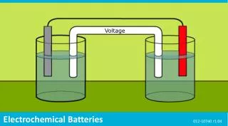
TRANSFORMER Transformers convert AC electricity from one voltage to another with a little loss of power. Step-up transformers increase voltage, step-down transformers reduce voltage. The input coil is called the primary and the output coil is called the secondary. There is no electrical connection between the two coils; instead they are linked by an alternating magnetic field created in the soft-iron core of the transformer.
555 TIMER • The 555 Timer IC is an integrated circuit (chip) implementing a variety of timer and multivibrator applications. • The original name was the SE555 (metal can)/NE555 (plastic DIP) and the part was described as "The IC Time Machine". • Depending on the manufacturer, the standard 555 package includes over 20 transistors, 2 diodes and 15 resistorson a silicon chip installed in an 8-pin mini dual-in-line package (DIP-8)
555 TIMER The 555 Timer IC is an integratedcircuit (chip) implementing a variety of timer and multivibrator applications • The 555 has three operating modes: • Monostable mode: in this mode, the 555 functions as a "one-shot". Applications include timers, missing pulse detection, switches, touch switches, frequency divider, capacitance measurement, pulse-width modulation (PWM) etc. • Astable - free running mode: the 555 can operate as an oscillator. Uses include LED and lamp flashers, pulse generation, logic clocks, tone generation, security alarms, pulse position modulation, etc. • Bistable mode or Schmitt trigger: the 555 can operate as a flip-flop, if the DIS pin is not connected and no capacitor is used. Uses include bounce free latched switches, etc.
1N4007 Diodes are used to convert AC into DC these are used as half wave rectifier or full wave rectifier. Three points must he kept in mind while using any type of diode.
The resistor, RS is connected in series with the zener diode to limit the current flow through the diode with the voltage source, VS being connected across the combination. The stabilised output voltage Vout is taken from across the zener diode. The zener diode is connected with its cathode terminal connected to the positive rail of the DC supply so it is reverse biased and will be operating in its breakdown condition.
BC547 • The BC547 transistor is an NPN Epitaxial Silicon Transistor. • The BC547 transistor is a general-purpose transistor in small plastic packages. • It is used in general-purpose switching and amplification BC847/BC547 series 45 V, 100 mA NPN general-purpose transistors. • Whenever base is high, then current starts flowing through base and emitter and after that only current will pass from collector to emitter
RELAY • IT IS A ELECTRO MAGNETIC SWITCH • USED TO CONTROL THE ELECTRICAL DEVICES • COPPER CORE MAGNETIC FLUX PLAYS MAIN ROLE HERE
Relay Driver ULN2003 • ULN is Relay driver application • The ULN2003 is a monolithic high voltage and high current Darlington transistor arrays. • It consists of seven NPN Darlington pairs that features high-voltage outputs with common-cathode clamp diode for switching inductive loads. • The collector-current rating of a single Darlington pair is 500mA. • The Darlington pairs may be paralleled for higher current capability.
Contd … • The ULN functions as an inverter. • If the logic at input 1B is high then the output at its corresponding pin 1C will be low.
LOAD INDUCTIVE LOAD: An inductive load consists of a load created by a wire wound coil, such as in a relay or solenoid, a transformer, or any load which uses a winding over a magnetic iron core. Breaking an inductive load is usually more severe than breaking a resistive load and will generally produce heavy arcing.