Download

1 / 27
430 likes | 746 Views
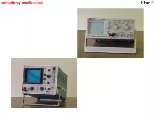
Cathode Ray Oscilloscope Introduction. Look and play Read instructions Break into smaller parts Decide on a simple measurement Increase your level of difficulty Record pathway. How you got there. Store directions and short-cuts. Cathode Ray Oscilloscope.

E N D
Cathode Ray Oscilloscope Introduction • Look and play • Read instructions • Break into smaller parts • Decide on a simple measurement • Increase your level of difficulty • Record pathway. How you got there. • Store directions and short-cuts
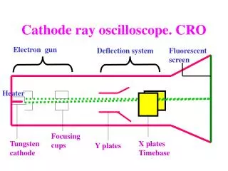
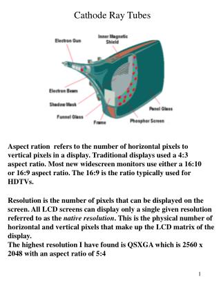
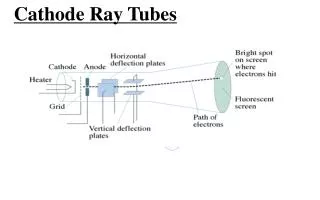
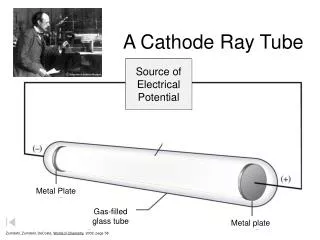
Cathode Ray Oscilloscope • Popular instrument to show time, voltage both DC and AC. Shows Volts / Time. • Display waveforms. Spectrum scope shows volts to Frequency • Cathode (-ve ) is heated, emits electrons, accelerated toward a (+ve) fluorescent screen. Intensity grid, Focus grid, Accelerating anode. (Electron gun) • Horizontal deflection plates. • Vertical deflection plates
Cathode Ray Oscilloscope • When electrons hit the screen the phosphor is excited and emits light. • Persistence. How long the display glows. • May need to reduce ambient light for older instruments. • Connect a signal to Vertical deflection plate. • At same time a voltage that increases linearly with time (Ramp) is applied to the Horizontal deflection plates.
This horizontal linear deflection is produced by the Sweep generator. • Sawtooth wave. • When the sweep signal returns to zero ie the end of the sweep, the beam flies back to the start position. The beam is cut off during the flyback time.
CROs • The display is made to appear stationary. • This controlled by your adjustment settings. • The eye sees a waveform. • X is <----> Horizontal • Y is ^ Vertical Height of trace
The signal is amplified by the vertical amplifier, applied to the vertical plates. • A portion of the vertical amp signal is applied to the Sweep Trigger. • The sweep trigger generates a pulse coincident with a selected point in the cycle of the trigger signal. • This pulse turns on the sweep generator initiating the sawtooth wave form. • The sawtooth wave is amplified by the horizontal amp and applied to the horizontal deflection plates
The trigger can be based on 50 (60) Hz • Provision is made for an external trigger.
CRO Tube Controls • POWER on / off • Scale • Illumination • Focus. Create spot on screen • Intensity. Brightness (Don’t burn a spot on your screen)
Vertical Amp • Position on display • Sensitivity of vertical amp Calibrated. Cal fully clockwise. • Variable sensitivity. Continuous range between calibrated steps. • AC - DC - Gnd. • Selects desired coupling for incoming signal, or grounds amp input. DC couples signal directly to amp. AC connects via a capacitor. (Blocks DC) • Gnd = no signal. Gnd connects Y input to 0 volts. Checks position of 0v on screen.
Horizontal Sweep • Sweep time / Div (or CM)Select desired sweep rate, or admits external sig to horiz amp. • Sweep time / Cm VariableContinuously variable sweep rates. Cal is fully clockwise. • PositionControls horizontal position of trace. • Horizontal variablecontrols attenuation of signal applied to Horz amp through Ext Horiz connector.
Trigger Set to Auto or normal • Trigger selects timing of the beginning of the Horizontal sweep. • Slopeselects trigger at +ve increasing or -ve decreasing portion of signal. • CouplingSelects whether trigger is at a specific DC or AC level. • Source: Int from Vertical Amp • Ext from Ext Trig Input. • Line AC line 50 (60) HZ
Volts /Div switch • Volts / Div • Variable Fine adjustment • these controls can have a Pull out switch position. May be 5 times mag.
Vertical mode • The operation of vertical deflection plates • Chan 1 and Chan 2 can each operate separately. • Dual. Ch1 and Ch2 are swept alternatively. • Why Dual? Used to measure input and Output signals of a device under test. • Ch1 and Ch2 can be added
Time base • Main, Max, Min, delay. • Selects the sweep for the main mix or delay mode and also X-Y switch • Time/Div provides selection of sweep rates. Range of 0.1 Second, 50 to .1 mS, 50 to 0.1uS per div. Note 5,2,1, sequence. • To determine a frequency use reciprocal. • Frequency = 1/time period (50Hz = 1/20mS) • Time period = 1/Frequency (number of div * ?ms/div. Eg 4div*5ms/div = 20 ms)
Other • Comp Test. Allows individual components to be tested. Connect via banana jacks to test resistors, capacitors, diodes, transistors, etc • Cal delivers calibrated voltage e.g. 2v p-p 1KHz square wave for setting scale. • GND. Earth terminal of scope
Connections • Vertical Input • Horizontal Input • External Trigger • Cal. Out
Bandwidth • A 10MHz CRO does not mean it will correctly measure signals at 10MHz. • Vertical Amps are not so wide-band as to amplify all signals. 10MHz is the 3dB point. A 10MHz signal of 1v will measure 0.707v on the screen. • Clipping introduces odd order harmonics. A CRO operating near the max freq. will not show the harmonics and you think you are reading a clean signal. • Square waves begin to look like sine waves. • A rule of thumb is 5 times. To measure 2MHZ use a 10MHz CRO. 3 times is suitable for most Amateur work. • For 7MHz. Times 3 = 21. Use a 20 MHz CRO.
Every CRO will be different • Many instruments made for specific work. • Beam Finder push button • Trace rotation • Chan 1 Vertical input. During X-Y operation this is X axis (abscissa) • Chan 2 Vertical input Chan 2. During X-Y this becomes ordinate input.
And there’s more ! • Don’t worry about it • Nothing is complex • Just Simplicity multiplied
Operating • Power on • Intensity fully counter-clockwise • Vertical centering in center of range • Horizontal centering in center of range • Vertical at 0.2 or 5v / div. Try a range. • Timebase 10ms / div Change to suit. • Play ‘till operating for you.
Mini exercises • Obtain a trace • Brightness • Focus • Move trace up, down. • Move trace side ways
Measuring • Voltage RMS is 0.707 * Vp for Sine and Cosine waveforms. • Hint: Try using a multimeter in parallel until you are happy with the measured CRO readings.
Mini exercise DC • Find a battery or a plugpack (Wall wart) • Determine approximate number of volts • Set vertical amp. Volts per Division • Cal. Control fully clockwise • DC (AC will show ripple component only) • Connect probe to battery • Read volts by number of volts per division on display.
AC Sine-wave • Decide upon probable frequency • Set timebase • Obtain display • DC or AC ?? • One or more cycles per division or whole display? • Volts per division (Vertical) Peak to Peak • Calculate RMS volts (Peak x 0.707)
Square wave • Decide upon probable pulses per second • Set timebase, Obtain display. • One or more pulses per division or whole display? • DC or AC ??? Try it. • Volts per division. Vertical • Pulses per division. Horizontal • Measure volts, Length of pulse.
Complex waves • AC ripple super imposed on a DC supply • Mixing two sine waves. Phase measurements. Lissajous patterns (X-Y) • Dual trace CROs • External Trigger ( Positive going and Negative going) • Noise • Frequency resolution of CROs.
Read your operating manual • Read your operating manual • Read your operating manual • Enjoy reading your operating manual. • Test old projects, AM radios. • Audio or RF oscillators • Read your operating manual - ENJOY