Download
1 / 19
190 likes | 324 Views
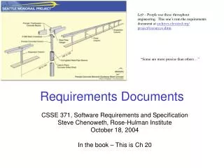
Overcoming Customer Constraints on Requirements Documents . Sub-Optimization of Systems Engineering. Presented by: Robert Smole. November 5, 2008. Agenda. Introduction Problem Approach Results Wrap Up. Introduction . Systems Engineering

E N D
Overcoming Customer Constraints on Requirements Documents Sub-Optimization of Systems Engineering Presented by: Robert Smole November 5, 2008
Agenda Introduction Problem Approach Results Wrap Up
Introduction • Systems Engineering • Means to enable the realization of successful systems – best practices • Considers both the business and the technical needs of all customers - constraints • What happens when the ‘business needs’ constrain the ‘best practices’?
Customer Constraints Systems Engineering Best Practices Why Sub-Optimal? • Find a balance. • Approach: Sub-optimal SE. • Agenda: Communicate the value of SE. • Goal: …to realize a successful system.
HIGHLY COMPLEX AND CHALLENGING PROGRAMS DEMAND SYSTEMS ENGINEERING Size: Length-1092ft, Weight-97,000tons Cost: Approx. $5-6 Billion Construction time: 6-7 years Design time: Approx 6 years from Concept Nimitz Class CVN A mobile, nuclear powered, survivable, sea-based super structure, capable of accommodating approx 5000 personnel, managing 75+ air combat vehicles, and conducting joint operations.
R1-1 NGSB-NN: Model-Based SE Approach Requirements Analysis Functional Analysis Physical Architecture Analysis • Define high level FA from ORD • Define mission/operational performance • Decompose functions to lowest level • Allocate performance requirements to functions • Develop FFBDs • Develop Operational Threads (sortie) • Determine common missions • Review top level requirements • documents • Decompose ORD • Derive Ship system Requirements • Flowdown to system requirements • Derive Functional / Performance • Requirements • Define System Structure • Define Internal/External Interfaces • Determine Island Alternatives • Establish product baselines • Define system design constraints • Allocate functions to systems/components Operational Scenarios, Conceptual Behavior Models Common Island Component Models Requirements Model F2 F3 R System F1 F5 Interfaces R1 R2 F4 Components Product Evaluation and Document Generation • Analyze Design & Assess Risk • Cost Assessment • Conduct trade studies • Select Best Design Solution • Automatic Document Generation • Provide Metrics Reports Analysis Results SRDs
Perform Requirements Analysis Capability Requirements Operational Requirements Derived Requirements System Requirements Ship Requirements Detail Requirements What are the requirements of your system? Where are your requirements managed? Concept of Operations Top Level System Level System Level System Level Component Level Component Level Component Level Validation Does the customer agree with our interpretation of the requirements? Develop Functional Solution What does your system do? What are the functions of your system? What are the requirements for each function? Top Level Architectural Set Verification Functional Architecture Physical Architecture Functional Flow Block Diagrams Does our system as-designed and as-built meet the system requirements as-validated? Contract Design Package System Diagrams Component & Context Diagrams Verification Cross Reference Matrix Develop Physical Solution System View What are the boundaries of your system? What are the components of your system? Detail Drawings Top Level Detail Design & Product Model Requirements Process Requirements Set Technical View Ship Specs
Problem • Update a System Requirements Document • Not configuration managed within the CASE tool. • Contained some or all of: “will”, “shall”, “may”, & “should” within requirement text. • Requirements within functional statements. • Requirements not singular (more than one “shall”). • Requirements not “stand alone”. • Definitions within the body of the document, not in appendix. • SRD used an outline format - multiple indents. • Interface requirements not mapped to interfaces on diagram.
Communicate Function Function 1 AND AND Function 2 Communicate Orders 3 Function 4 Function 5
Improper Use of the CASE Tool Function 1 Requirement(s) Requirement(s) Requirement(s) Function 2 Communicate Orders 3 Requirement(s) Requirement(s) Function 4 Liabilities: Traceability, Verification, Decomposition Function 5
Requirements Imbedded within Functions 3.1.3 Communicate Orders • The _____ subsystem shall be the primary means of communicating orders. • The _____ subsystem with interfaces to the _____ shall provide supplementary communications. • Main Deck Communications Capability • The _____ subsystem shall be the primary means of communication for the coordination of operations on the Main Deck. • The _____ subsystem with interfaces to the _____ shall provide supplementary communications. • 2nd Deck Communications Capability • The _____ subsystem shall be the primary means of communication for the coordination of operations on the 2nd Deck. • The _____ subsystem with interfaces to the _____ shall provide supplementary communications. • Engine Room Communications Capability • The _____ subsystem shall be the primary means of communication for the coordination of operations in the Engine Room. • The _____ subsystem with interfaces to the _____ shall provide supplementary communications.
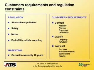
Constraints • The overall document format and layout had to remain consistent with the original document which was not consistent with standard SRD formatting. • Definitions and lead-in statements had to remain in their relative location (could not move the definitions to an appendix). • “May” was acceptable - there are some design targets that are not ‘hard’ requirements (they don’t have to meet these).
Approach • Moved all the ‘requirements’ from Word to Excel. • Parsed the ‘requirements’ from the functions. • Separated multiple shall statements. (singular requirements) • Placed definitions in Requirement Objects and marked the Verification Method as ‘n/a’ to identify it as ‘not a requirement’. • Standardized on the use of “shall” to denote requirements.
Approach • Allowed the use of “may” for design targets (these are not requirements). • Used the spreadsheet to provide a comparison to the baseline. • Decided on an iterative approach to ‘fix’ the SRD. • Further changes to structure (ie, interface linking) in future revisions. • Migrated requirements to the CASE Tool (Cradle) and used this tool to generate the Rev B SRD.
Result (example) 3.1.3 Communicate Orders This function communicates orders a) Communicate Orders - 1 The _____ subsystem shall be the primary means of communicating orders. b) Communicate Orders - 2 The _____ subsystem with interfaces to the _____ shall provide supplementary communications. c) Main Deck Communications Capability - 1 The _____ subsystem shall be the primary means of communication for the coordination of operations on the Main Deck. d) Main Deck Communications Capability - 2 The _____ subsystem with interfaces to the _____ shall provide supplementary communications. e) 2nd Deck Communications Capability - 1 The _____ subsystem shall be the primary means of communication for the coordination of operations on the 2nd Deck. … … …
Communicate Function - Revisited Function 1 AND AND Function 2 Communicate Orders 3 Function 4 Function 5
Proper Use of the CASE Tool Function 1 Function 2 Requirement(s) Requirement(s) Requirement(s) Communicate Orders 3 Function 4 Requirement(s) Requirement(s) Function 5 Allows: Traceability, Verification, Decomposition
Wrap Up • Considerations • New Design? • Roll-over Design? • Commercially Available Products? • Integrating Other Systems? • System Complexity? • Essentials • Interface Requirements. • Traceability. • Verification. • Non-Essentials • Document Format/Layout. • One step at a time = progress toward full SE