Download
1 / 22
360 likes | 701 Views
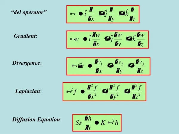
Use of Phase Gradient Autofocus (PGA) for Refocusing Rocking Ships in Spotlight-Mode SAR Imagery Dr. Charles “Jack” Jakowatz, Jr. Sandia National Laboratories Albuquerque, NM cvjakow@sandia.gov Purdue University West Lafayette, IN 26 September, 2003. Collection Geometry for Spotlight-Mode SAR.

E N D
Use of Phase Gradient Autofocus (PGA) for Refocusing Rocking Ships in Spotlight-Mode SAR Imagery Dr. Charles “Jack” Jakowatz, Jr.Sandia National LaboratoriesAlbuquerque, NM cvjakow@sandia.gov Purdue UniversityWest Lafayette, IN26 September, 2003
Three-Dimensional Phase History Data for Spotlight-Mode SAR The angular extent of the annulus is determined by the flight path. It prescribes the azimuthal resolution of the formed SAR image This dimension of the annulus is determined by the radar bandwidth and prescribes the range resolution in the formed SAR image The offset of the phase history data from the origin is directly proportional to the radar center frequency q
Phase Errors in SAR Imagery • Recall that for each position of the aircraftfrom which a pulse is transmitted and received, the deramp processor must “know” precisely when the returned echo arrives. • Inevitably, there will be some uncertainty in this time, because the aircraft position is never known without some amount of error. • For an aircraft position error in the along-line-of-sight (range) direction of only a half wavelength, a full 2p of phase error occurs.
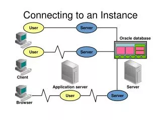
Uncompensated Aircraft Position Errors Lead to Phase Errors in the Collected SAR Phase History Data Aircraft Position Errors Lead to Phase Errors in Collected Data
Three-Dimensional Phase History Data for Spotlight-Mode SAR The angular extent of the annulus is determined by the flight path. It prescribes the azimuthal resolution of the formed SAR image This dimension of the annulus is determined by the radar bandwidth and prescribes the range resolution in the formed SAR image The offset of the phase history data from the origin is directly proportional to the radar center frequency q
Cartesian raster Image is formed by 2-D IFFT of data interpolated to the Cartesian raster Effect of the phase error function is to blur the formed image in thecross-range (x) dimension
Defocusing Due to Phase Errors in a Spotlight-Mode SAR Image When the interpolated samples are coherently integrated via compression (Fourier transformation), the phase errors cause defocusing of the formed image in the cross-range dimension. The resulting blurred image is a convolution of the desired image with: IFT{exp( j phase error function)}
Removal of Phase Error Effects in SAR Imagery • The only way to remove the residual defocus effects is to estimate the phase errors from the blurred image itself. • Such a technique is known as a “data driven” algorithm. • It amounts to “blind” deconvolution of the degrading phase error function. • Sandia Laboratories developed the Phase Gradient Autofocus algorithm (PGA) in 1989 as a solution to this problem (Jakowatz, Eichel, and Ghiglia)
PGA Results Image defocused from uncompensated aircraft position errors Image refocused using PGA
Autofocus by PGA of 2-inch Resolution Sandia LabsTwin Otter Spotlight-Mode SAR Imagery Vehicles at National Guard Armory Official Use Only
Attempt to Refocus Image of Rocking Ship from LYNX Spotlight-Mode SAR (16 GHz) Using PGA Original Global PGA Space-Variant PGA After PGA Note: Vertical Lines Indicating OSA Boundaries Before PGA
Attempt to Refocus Image of Rocking Ship from LYNX Spotlight-Mode SAR (16 GHz) Using PGA Original Global PGA Space-Variant PGA Note: Vertical Lines Indicating OSA Boundaries
Attempt to Refocus Image of Rocking Ship from LYNX Spotlight-Mode SAR (16 GHz) Using Spatially-Varying Version of PGA Original Global PGA Space-Variant PGA Note: Vertical Lines Indicating OSA Boundaries
Ship Motion (Rocking) Correction Lynx20030302220035 Phase Error Function Space-Variant PGA
Refocused Image of Rocking Ship from LYNX Spotlight-Mode SAR (16 GHz) Using Space-Varying PGA Original Global PGA Space-Variant PGA After Space-Varying PGA Note: Vertical Lines Indicating OSA Boundaries Before PGA
Foliage Penetration (FOPEN) • SAR is all-weather, day/night capable • Typical SAR frequencies have difficulties penetrating foliage • Use different radar frequencies (VHF) to achieve penetration • Typically, resolution suffers with these lower frequencies • Use high resolution systems, coupled with a 3-D approach 3-D tomography from multiple data collects can be used to address the problem of foliage penetration