Download
1 / 26
260 likes | 397 Views
Plasma Current Start-up Experiments without the Central Solenoid in TST-2 and Future Plans. Y. Takase Graduate School of Frontier Sciences, University of Tokyo for TST-2 and TST-2@K Groups. Joint Meeting of the 3rd IAEA Technical Meeting on Spherical Tori

E N D
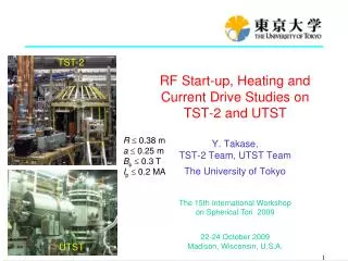
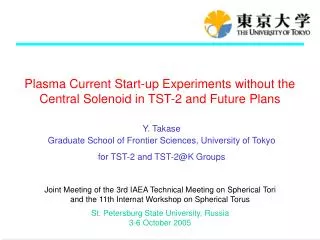
Plasma Current Start-up Experiments without the Central Solenoid in TST-2 and Future Plans Y. Takase Graduate School of Frontier Sciences, University of Tokyo for TST-2 and TST-2@K Groups Joint Meeting of the 3rd IAEA Technical Meeting on Spherical Tori and the 11th Internat Workshop on Spherical Torus St. Petersburg State University, Russia 3-6 October 2005
Motivation for CS-less Ip Start-up Compact, high bplasma with good confinement can be realized in ST compact burning plasma experiment and fusion reactor Lower aspect ratio and elimination of central solenoid (CS) improves economic competitiveness
TST-2 TST-2 Spherical Tokamak • Design parameters of TST-2: • R = 0.38 m / a = 0.25 (A = 1.6) • Bt = 0.3 T (0.3 T achieved) • Ip = 0.2 MA (0.14 MA achieved) • tpulse = 0.05 s (0.3 s achieved) • Main research topics: • Plasma start-up optimization • RF heating and wave physics • MHD instability and reconnection • Control of turbulence and transport
Relocation of TST-2(Twice in 2 Years) TST-2 U. Tokyo Kashiwa 2004~ U. Tokyo Hongo ~2002 Kyushu U. Fukuoka 2003
TST-2 at Kyushu University (2003) TST-2@K Waveguides from 8.2GHz klystrons Heating / current drive By ECW and/or EBW Typical plasma equilibrium TST-2 EBW Antenna
Plasma Stored Energy Increase (Heating)Observed during RF Injection TST-2@K RF on no RF Wkin 15% increase in Wtotal Wtotal = Wkin + Wmag(pol)
Plasma Current Formation by ECH TST-2 • 1 kA / 1 kW achieved by ECH (2.45 GHz) • Higher current for low gas pressure low collisionality is important • Requires vertical field with positive curvature trapped particles are important
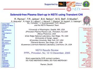
Solenoidless Start-up Experiments TST-2@K no w = wce res. inside vac.ves. • Forest scenario • “pressure driven current” with mirror Bv • 4kA maintained for 0.27 s (with static Bv ~ 2 mT, no induction) • Te = 160 eV (plasma is collisionless)
Reconstructed Equilibrium of the RF Start-up Plasma (I) 0.8 Plasma is limited by the outboard limiter, jf is truncated at top and inboard 0.4 Z [m] 0 -0.4 -0.8 0 0.4 0.8 R [m]
Features of RF Start-up Plasma Equilibrium jf [kA/m2] @ z=0 0 • high bp • large outboard boundary current Outboard co-PS current is dominant, while inboard counter-PS current is truncted. • Steep pressure gradient at the outboard boundary -80 0 0.7 R [m] p [Pa] @ z=0 4 Soft X-ray flux and temperature are roughly consistent with the pressure deduced from equilibrium reconstruction. 0 0.7 0 R [m]
Completely CS-less Start-up to Ip = 10 kAAchieved in TST-2 TST-2@K PF1 PF2 6 turns PF4 PF3 24 turns PF5 1 turn CS
New Start at the Univ. Tokyo Kashiwa Campus TST-2 • Resume operation at Kashiwa • Solenoidless start-up • Based on results of JT-60U • Reconnection physics • Reconnection Events • Ion heating • Turbulence and transport • Develop fluctuation diagnostics • HHFW heating / current drive • 10-30MHz / 400 kW • k|| control (new antenna) • Prepare LHCD system • 200MHz / 400kW (from JFT-2M)
100kW of RF Power Injected Successfully TST-2 HHFW Antenna Full-wave calculation by TASK/WM Eq Bt = 0.3 T, f = 21 MHz, n = 10, ne = 2 1019 m-3, Te = 0.3 keV
Preparation in Progress for 200 MHz Experiments TST-2 Full-wave calculation by TASK/WM 200 MHz transmitters (from JFT-2M) Eq Combline antenna Bt = 0.3 T, f = 200 MHz, n = 10, ne = 2 1018 m-3, Te = 0.3 keV
Reconnection Events TST-2
Detailed Time Evolution t=26.6ms t=26.2ms Ip TST-2 40.0 15.0 26.0 27.0 25.0 radiation 2.0 0.0 2.2 H_alpha 2.0 q_0 0.0 2.2 Hard X ray 4.0 1.4 1.4 27.0 26.0 0.0 25.0 li -4.0 0.76 mag. fluct. 1.0 0.71 -1.5 W(J) log(b^2) 50.0 -1.0 -5.0 20.0
Ion Heating Observed at Reconnection Events TST-2 Conversion of magnetic energy to ion kinetic energy Reconnection events CV intensity decreases while CIII, OIII intensities increase (loss of electron energy) CV (core), and OV, CIII, OIII (edge) ion temperatures increase at reconnection events
A New Experiment to Explore Ultra-High b Plasma Formation by Plasma Merging UTST
a a Rapid Heating by Plasma Merging / Reconnection TS-3 120 Merging I =0 Megawatts of heating power can be obtained by plasma merging / reconnection tfc Y. Ono, et al. dW/dt 80 ~10[MW] 40 Single FRC 0 I =10kA tfc 80 Merging ST#1 ST#2 dW/dt B B B p p p 40 ~6[MW] Single Low q ST I I z 0 z B +B t ext B +B B +B t ext High b ST t ext I =35kA tfc dW/dt 80 ~4[MW] Merging Comparison of thermal energy evolution for merging (solid line) and single (dashed line) formation 40 Single High q ST 0 10 20 30 time [msec]
Start-up without Center Solenoid Demonstrated JT-60U • VTin coil disconnected • Use VR and VTout only • Discharge duration increases with • improvement of plasma position control
Demonstration of Advanced Tokamak Operation without the Center Solenoid JT-60U Noninductive ramp-up Start-up and initial ramp-up Transition to self-driven phase 2002.06.21
Profiles of CS-less Advanced Tokamak with Very High Self-Driven Current Fraction JT-60U ITB + H-mode (Ip = 0.7MA) bp = 3.6, bN = 1.6, HH = 1.6, fBS > 90% transport barriers
Backup(I) 0.8 The following flux function was tried, but parameters a and g were not efficient. PF2 Coil 1st 2nd 3rd 0.4 Z [m] 0 This implies that the present magnetics cannot resolve edge fine structure. Antennas -0.4 V.V -0.8 0 0.4 0.8 R [m] External poloidal field
Backup (II) Pickup coils Flux loop poloidal angle Flux function (red) and area of large jf (blue). Fitting was poor for inboard Bz