Download

1 / 34
340 likes | 429 Views
Failure Mode, Effects, and Criticality Analysis (FMECA) Last revised 08/10/2005. Introduction.

E N D
Failure Mode, Effects, and Criticality Analysis (FMECA) Last revised 08/10/2005
Introduction The FMECA toolkit provides most of the analyses commonly associated with a FMECA analysis. It supports the accomplishment of Task 101 (FMEA) and Task 102 (Criticality Analysis). In addition, you can use the toolkit to perform Testability Analysis and Reliability Centered Maintenance for each failure mode in the system. ASENT’s FMECA Manager supports functional, hardware, or combined FMECAs, and its methodology allows you to do top-down or bottom-up FMECAs. Assemblies, boards, functions, parts, and signals can be modeled along with related failure modes and effects. The relationship between failure modes and effects and the tree structure are automatically tracked by the toolkit so that updates can easily be made at any time.
Recommended Methodology Hint: refer to the FMECA Manager online help. Refer to the ‘Using the FMECA Manager’ help book.
Starting A New FMECA The FMECA Manager is the tool in ASENT that is used to perform FMECAs. From the ASENT Session Manager, right-click on your project and select the FMECA Manager from the drop-down menu. The first time that you enter the FMECA Manager for a project it will ask you to select a project to copy libraries from. This gives you the ability to start your FMECA by leveraging off of FMECA data that may already exist for other projects. This can be very helpful when performing an analysis on equipment that is similar, where a FMECA already exists.
Initializing FMECA Libraries If in doubt, just select the COMMON_FMD91 project. This should be highlighted as the default. This project is empty except it contains part types and their failure mode distributions. This is particularly helpful if you are performing a piece-part level FMECA. Select what data you want copied from the selected project library to your FMECA project. If in doubt, leave everything checked and click the OK button. If you want a totally blank library, then uncheck all of the boxes and click the OK button. User selects the COMMON_FMD91 project to use as their default starting point.
Defining A Function/Phase Next, you will create the function/phase for your FMECA. ASENT allows you to have as many function/phase combinations as you want. These are treated like separate projects within a project. These are used to keep track of the data associated with different modes of operation. For example, you may have a FLIR with a function of Surveillance Mode. Maybe it has a Daytime phase and a Nighttime phase that need to be analyzed separately.
Importing the Reliability Tree Normally, when performing a FMECA, a good starting point is to import the Reliability tree. Once imported, the user can add or delete items, and modify the data, since you have full tree editing capability in the FMECA. This is important, because often, there will be portions of your system that you may want to model functionally in the FMECA. In the FMECA tool you can import trees or sub-trees from either the Reliability tree or other FMECA trees. If you import the Reliability tree then the FMECA tree will automatically be linked to it. If later, you have to modify descriptions or reference designator values, modify these in the Reliability tree, and simply use the FMECA Update Links option, from the project node, to make these changes in the FMECA. You can sever the links or re-link tree nodes anytime in the future.
Importing the Reliability Tree To import the Reliability tree, right-click on the project node and select the ‘Import’ option from the drop-down menu. When the Import window appears, select ‘Reliability Manager Trees’ and click the OK button.
Importing the Reliability Tree Next, a list of projects appear. Locate your project name in the list and select it, then click on the OK button. After the project has been selected, a window will be displayed showing the product tree. Initially, the tree is collapsed and only the project node is shown. Select the project node and click on the OK button.
Importing the Reliability Tree Once you have selected the project node of the Reliability tree and clicked OK, then you will be prompted for some additional data. First, you will be asked whether or not to overwrite the existing FMECA tree. Answer ‘Yes’ so that the FMECA tree becomes a copy of the Reliability tree. If you answer ‘No’ it will append it off the project node of the FMECA tree. Next, you will be asked whether or not to import parts. If you are doing a piece-part level FMECA then you should answer ‘Yes’. If not, then select ‘No’. Finally, if you chose to import parts, then you will be asked whether or not to default the failure modes for each of the parts. ASENT does this by using the Part Type/Failures library, which is built into the FMECA. Normally, if you are importing parts, then you would want the failure modes automatically defaulted for these parts, so answer ‘Yes’ to this prompt.
Extensive use of libraries reduces data entry and errors Data entry and errors are significantly reduced by the extensive use of libraries in the tool. The FMECA Library Editor contains data tabs to access various types of library data. Libraries exist for failure modes and effects, signals, part types and their corresponding failure modes, and detection or test codes. The navigations buttons and their meanings are shown below.
Part Types/Failures Library Here, the default failure modes and their failure distributions are displayed for a Bipolar Digital Microcircuit. The user can select either the RAC FMD-91, MIL-HDBK-338, or their own library for part type failures. This feature virtually eliminates the need to enter failure modes for parts when doing a piece-part level FMECA.
Adding Failure Modes To add failure modes for an item, right-click on its corresponding FMs container and select the ‘Add’ option from the drop-down menu. Here, we are adding failure modes for the PWRCNV.
Adding Failure Modes Failure modes can be added by either selecting a failure mode that exists in the library, or it can be added on the fly. Click here to select a failure mode from the library. Click here to add a new failure mode on the fly.
Adding Failure Modes that exist in the library This screen shows the user selecting a failure mode from the library. This picklist has an active search capability, so if you start typing, it will immediately jump down to the first failure mode that contains your string.
Adding Failure Modes on the fly When the user is adding failure modes for an item and they select the button, then the following screen appears. This screen allows the user to enter a failure mode that was not previously defined in the failure mode library. The name field will handle 255 characters. Enter the failure mode in the Name field and click OK. Then, click on the Save button to add the failure mode.
Working with Failure Modes Individual failure modes or groups of failure modes can be copied and moved from one location to another. The CTRL-Drag-and-Drop accomplishes a copy and the Drag-and-Drop accomplishes a move. Hint: Refer to the FMECA Manager online help for detailed instructions on working with failure modes. Refer to the ‘Working with Failure Modes’ help book.
Entering Failure Mode Ratios Failure Mode Ratios should only be entered at the lowest level in the tree structure. For example, if you are doing a piece-part level FMECA, then failure mode ratios should be filled in for each failure mode at the part level. If ASENT was told to default the failure modes for the parts, then this will happen automatically. If the lowest level in your tree structure is a function or a circuit card, then at this level the failure mode ratios need to be filled in. The failure mode ratios for all of the failure modes associated with intermediate nodes should be left blank. Right-click on the project node and select the ‘Roll-up Failure Mode Ratios’ option to calculate these values.
Evenly Distribute Failure Mode Ratios ASENT has the ability to evenly distribute the failure mode ratios among all of an item’s failure modes. To do this, merely right-click in the grey area above the Description, and select the ‘Distribute FM Ratios’ option.
Defining Next Higher Effects The failure mode that we are assigning Next Higher Effects for. Use these buttons to Add or Remove Next Effects. List of modes at the NHA that have not been selected.
FMECA Manager product tree display Here, the FMECA Manager displays the product tree structure for the Radar / Operating phase that is being analyzed. By selecting the Failure Mode (FMs) container on the project node the user is able to view or edit the system level (End) effects.
User selects a single effect to analyze Notice, when the user selects a single failure mode or effect the data for that item is displayed on the right side. Also, the user can select the Causes tab to view the failure causes, enter compensating provisions, remarks, the detection method, or perform testability analysis. At the RIU or PWRCNV levels in the tree the user would also be able to view / edit the Next Higher Effects.
Viewing the causes of a system level effect The user views the failure causes for the highlighted system level effect by clicking on the Causes tab. Here, a bit circuit failure on the RIU causes a bit circuit failure on the system.
Viewing the End Effects of a Failure Mode The user can easily view all the End Effects for a failure mode by selecting the End Effects Tab. This informs him if the Criticality Calculations are current and shows the criticality, severity and conditional probability.
Adding & Viewing Graphics The user can add graphics to the tree, or view the graphics for an assembly by selecting ‘Graphics’ from the pop up menu.
FMECA Manager Menus Failure rates in the FMECA can easily be updated with new prediction results from the Reliability Manager. The tool calculates Criticality and Fault Detection / Isolation. Extensive reporting capabilities exist, including a user defined report feature.
Built-in Completeness Checker The Check FMECA utility checks your analysis and pinpoints any areas where needed data is missing. This time saving feature helps ensure that your analysis is complete. In spreadsheets and many other tools this is usually performed manually by the user.
Completeness Checker Results Here, the completeness checker reports that the LOSS OF 5 VOLTS A failure mode does not have a Next Higher Effect, and that the Criticality numbers have not been calculated.
Finding Data in the FMECA The Find menu makes it easy to find items within your FMECA.
Fault Detection / Isolation Here, the user defines the detection / isolation groups to determine test coverage. For example, the SRA TEST group uses test points to isolate failures to the component level. The Isolation Group sizes are defined as <=4, <=8, and <=10 components. Refer to the Testability Analysis tutorial for more details.
Leverage the existing Failure Mode Analysis The user enters detection / isolation information at the lowest level, and then intermediate values are calculated. Here, an Improper Config Resistor failure is detected by the SRA TEST group using testpoint J1-92. It isolates the failure to the R0005 component.
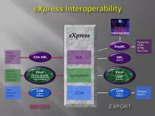
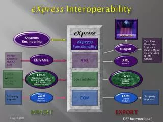
Importing / Exporting Data Data from the FMECA can easily be exported to Diagnostician for further Test Coverage development or to Logan for Fault Tree Analysis, creating significant savings of time and money in performing these analyses. Failure Mode data may also be imported from an Excel spreadsheet