Download

1 / 34
2.38k likes | 8.21k Views
PFMEA Process Failure Mode and Effects Analysis. James Davis, General Dynamics. Purpose.

E N D
PFMEAProcess Failure Mode and Effects Analysis James Davis, General Dynamics
Purpose The purpose of this presentation is to share the benefits of a detailed Process Flow Diagram, conducted during a Process Failure Mode and Effects Analysis, that will ensure product quality in the manufacturing/assembly process.
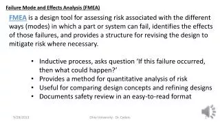
Definition of FMEA A FMEA is an analytical tool that uses a disciplined technique to identify and help eliminate product and process potential failure modes. • By ID of potential failures • Assessing the risks caused by failure modes and Identify corrective actions • Prioritizing corrective actions • Carry out corrective actions
Most COMMON Types of FMEA's Design (Potential) Failure Modes and Effects Analysis-DFMEA • Focus is on potential design- relatedfailures and their causes. Process (Potential) Failures Modes and Effects Analysis-PFMEA • Focuses is on potential process failures and their causes.
Value of FMEA's • Aids in improving designs for products and process • Increased safety • Enhances Customer Satisfaction • Better Quality • Higher Reliability • Contributes to cost savings • Decreases warranty costs • Decreases waste, non-value added operations
PFMEA's • Focus is on potential process –related failures and their causes. • Main drive is to understand the process through the identification of as many potential failures as possible. • e.g. Incorrect material used • PFMEA typically assumes that the design is sound. • Development of Recommended Actions is targeted at eliminating the Root Cause of the potential failures.
PFMEA Three Parts: • Process Flow Diagram (PFD) • Process Failure Mode and Effects Analysis (PFMEA) • Process Control Plan (PCP)
Information Flow Customer Requirements: SOR, Vehicle Tech Specs, System Technical Specs Product Definition: Key Product Characteristics, DFMEA Process Definition: Process Flow Diagram (PFD), Product and Process Characteristics Failure Mode Analysis: PFMEA Control Strategy: Control Plan, Error proofing Manufacturing: Work Instructions & Process Monitoring
DFMEA/PFMEA Information Interrelationships Boundary (Block) Diagram, P- Diagram, Etc. Process Flow Diagram DFMEA Design FMEA PFMEA Process FMEA Process Control Plan Design Verification Plan & Report (DVP&R)
Process Flow Diagrams • The Process Flow Diagram provides a logical (visual) depiction of the process that is being analyzed.
The SAE/AIAG PFMEA guidelines describe two methods of defining process functions. Either or both may be used. Process Functions may be described in terms of: The product features/characteristics that are created or The process actions that are performed Process functions should be identified in detail as necessary to provide information for the PFMEA to develop effective Process Controls Process Function / Requirement 12
Consider a simple operation to drill a hole in a metal part The product characteristics & requirements are: Hole size: 4.00 mm +/- 0.13 Hole Location:X = 28.0 mm +/- 0.2 Y = 15.0 mm +/- 0.2 Perpendicular to surface, no burrs, etc. The process operation must create these product characteristics and meet the requirements Process Function / Requirement Y X 4.00 13
To drill the correct hole size in the specified location, the process must: Position and hold the part Align the part fixturingwith the drill position Assure the correct drillbit size is used Set and control drill speed Anticipate tool wear andschedule preventive maintenance If the Function/Requirement is defined in the PFMEA as “Drill Hole” could any of these be missed? Process Function / Requirement
Process Flow Diagram (PFD) • Process Flow Diagram is the foundation • The process must be defined step by step, including interfaces • The PFD provides the structure to document what product characteristics and requirements (OUTPUTS) are affected by a given operation and how these characteristics and sources of variation are controlled (INPUTS) • PFD is a graphical representation of every possible path a part can take through the anticipated manufacturing process • A well defined PFD establishes the foundation for the PFMEA • Helps in developing equipment specifications. • How will the process control non-conforming material? • How and when will inspections be performed, what is required? • How and when will parts be re-introduced into the process?
Process Flow Diagram (PFD) • Hidden Factories: • Interfacing Processes Quality Audits Product/tooling Changeovers Rework Processes Part Ident./Labeling Alternative Processes Teardown Scrap Gauging Stations Part Buffers Reject Handling Part Movement • Interface process issues affect quality performance • Rework and scrap parts bypass process controls • Mixed parts in the manufacturing process at changeovers • Need for common systems • Part of the overall Quality Strategy must include • Common content, common format, common approach • Quality strategy must extend to suppliers • Considered an extension of the Total Quality processes
PFD Feeds PFMEAIdentify the Function(s) • Function is a description of what the Process does to meet the requirements • Related to process specification and product characteristics • Comes from the PFD operation description column • Functions can be described as: • Do this operation… • To this part or material… • With this tooling or equipment…
PCP will be based on the previous activities in PFD and PFMEA. Review the PFMEA information developed & supplied and use to identify: Specific controls that may be needed due to the information added Identify which controls are Product or Process Note any Special Characteristics Identify evaluation methods, frequency and Control Methods Note Reaction Plans (particularly related to NC parts) Process Control Plan
Process Control Plan Example Form 818-1 (Rev 12Apr02) CONTROL PLAN Prototype Pre-Launch Production Control Plan No: Part Number/Latest Change Level Key Contact/Phone Date (Orig.) Date (Rev.) Customer Part Number Core Team Customer Engineering Approval/Date (If Req'd.) Part Name/Description Supplier/Plant Approval/Date Customer Quality Approval/Date (If Req'd.) Supplier/Plant Supplier Code Other Approval/Date (If Req'd.) Other Approval/Date (If Req'd.)
Process Control Plan Example Part/ Process Number Process Name /Operation Description Machine, Device, Jig, Tools for Mfg. Characteristics Special Char. Class. Methods Reaction Plan No. Product Process Product / Process Specification /Tolerance Evaluation MeasurementTechnique Sample Control Method Size Frequency 300 Initiate weld sequence / Close and latch curtain Robotic Arm TIG welders . 300. Initiate weld sequence /Perform TIG weld of frame parts. Robotic Arm TIG welders and controllers. Weld beads per design specification. Tube welds meet pull test with failure in parent material. Pull test using test fixture 20-1. 1 pc. Per shift. Hydraulic pull test instruction TI41-01 Process monitoring form PM-20-010 Quarantine material since last good pull test. Good welds, no visible defects. yes Weld appearance meets visual standard. Operator evaluation to Visual Std TB20-VS1. 100% Each piece. Visual inspection OWI #20-010. Remove part and send to repair. Initiate weld sequence / Confirm Weld voltage Weld voltage yes 24 Volts AC+/- 2.0 volts Machine Control 100% Each weld cycle. Closed-loop machine control. Scrap part & Re-start welder Weld voltage yes 24 Volts AC+/- 2.0 volts Visual Once each Shift start or change-over or maint. event Set-up OWI #20-02 & Form PM-20-02 Periodic maintenance per PM-WI #20. Scrap current part. Shut down.Notify maintenance. Visual twice Per shift. Operator cleans gas cup twice per shift PM-WI-2500. Process monitoring form PMF-20-10 Notify maintenance. Inert gas flow rate yes 5 cubic feet / min.+/- 0.5 cfm Initiate weld sequence / Confirm Inert Gas flow rate Set-up OWI #20-02 & Form PM-00-02. Equipment Calibration Procedure #368 Inert gas flow rate yes 5 cubic feet / min.+/- 0.5 cfm Visual verification of Flow Meter Once each Shift start or change-over or maint. event Quarantine material since last good pull test. Notify maintenance. Initiate weld sequence / Confirm Wire feed rate Closed-loop machine control. Weld wire feed rate yes 300 mm / minute+/- 10 mm / min. Machine Control 100% Each weld cycle. Scrap part & Re-start welder Set-up OWI #20-020 & Form PM-20-020 Predictive maintenancepinch roller replace @ 180 days. Weld wire feed rate yes 300 mm / minute+/- 10 mm / min. Operator setup check and verification 100% Shift start or change-over or maint. event Scrap current part.Shut down.Notify maintenance.
Case Studies – Supplier A • Not ISO Certified, Primarily Defense business base • Sole Source - Unique Technology • No Process Flow • Operator work instruction for 100 piece component • 20 process steps on a single piece of paper (included machining) • Building the component relied on Tribal Knowledge • Diagramming the Process Flow • 20 steps turned into 951 steps to produce the component • 22 manufacturing related issues (from DFMEA) were incorporated in the PFD/PFMEA • Supplier A used PFD - FMEA to • Develop work instructions • Determine the requirement to developed training programs for assemblers / machinists, QC personnel • Develop safety program / training
Case Studies – Supplier B • ISO Certified, Primarily Defense business base • Sole Source - Unique Design • “Fair” Documented Process Flow • Relied on a combination of operator knowing what should be done next with operator work instructions. • However it did allow for repeatable assembly of component with skilled employee • Diagramming the Process Flow • 270 step PFD became 1,170 steps • FMEA analysis determined: work instructions that needed improvement and new work instructions were required • Supplier B used PFD- FMEA to • Update work instructions to error proof build process
Case Studies – Supplier C • ISO Certified, Defense/Civil business base • Well Documented Process Flow • Operator work instructions allowed for repeatable assembly • Error Proofing allows for assembly with “average” employees • Diagramming the Process Flow • 263 step PFD became 268 steps • 32 manufacturing related issues (from DFMEA) were incorporated in the PFD/PFMEA • FMEA analysis determined: work instructions that needed improvement and new work instructions were required • Supplier C used PFD- FMEA to • Update work instructions
Case Studies – Supplier D • ISO Certified, Aerospace business base • Very Small Company • 2 Master Assemblers (1 of which was the Assembly & Test Manager) • Unique Technology • “Fair” Documented Process Flow • Relied on a combination of operator knowing what should be done next with broad operator work instructions. • However it did allow for repeatable assembly of component with highly skilled employee • Diagramming the Process Flow • 5 page PFD became 22 pages • FMEA analysis determined: work instructions needed improvement to allow for production of more than 1 component at a time • Supplier D used PFD - FMEA to • Develop work instructions with boundary photos • Recall non-compliant parts • Determine the requirement to developed training programs for assemblers, QC personnel • Develop detailed ATP
Recapping Process Flow Diagram “What does the process do? PFMEA “What could go wrong?” “Could we prevent or detect?” Control Plan “What needs to be controlled/monitored?” “How do we react to problems?” Operator Instructions & Monitoring “What am I supposed todo?” “How am I supposed to do it?” “Where am I supposed to record it?” 32
References • AIAG FMEA Fourth Edition June 2008 • SAE J1739 March 2009
Vocabulary • AIAG FMEA Fourth Edition Published June 2008 • SAE FMEA J1739 Published March 2009 • PFD, Process Flow Diagram • PFMEA, Process Failure Modes and Effects Analysis • PCP, Process Control Plan