Download
1 / 17
170 likes | 291 Views
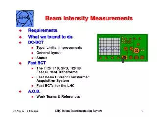
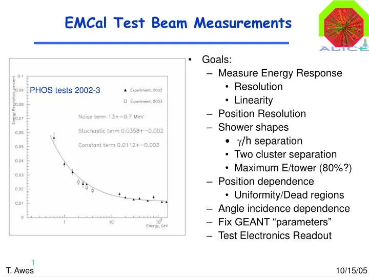
EMCal Test Beam Measurements. Goals: Measure Energy Response Resolution Linearity Position Resolution Shower shapes g /h separation Two cluster separation Maximum E/tower (80%?) Position dependence Uniformity/Dead regions Angle incidence dependence Fix GEANT “parameters”

E N D
EMCal Test Beam Measurements • Goals: • Measure Energy Response • Resolution • Linearity • Position Resolution • Shower shapes • g/h separation • Two cluster separation • Maximum E/tower (80%?) • Position dependence • Uniformity/Dead regions • Angle incidence dependence • Fix GEANT “parameters” • Test Electronics Readout PHOS tests 2002-3
Test Beam Scheduled at FNAL • We have been approved (MOU_T591) to run at the FNAL Meson Test Beam Facility: http://www-ppd.fnal.gov/MTBF-w/ • Mixed beams of e and p (K,p) from few GeV/c to 120 GeV/c (fractions/rates depend on momentum) - good match to our needs. • Scheduled for 1 shift of setup Friday Nov.4 followed by parasitic use of beam during following week while MOU_T590 (J-PARC straw tubes) is primary user. During this week we can continue setup, debugging, and begin gain matching, test shaping time difference and perhaps make decision on which to emphasize. • Primary user during weeks of Nov.14 and Nov. 21 (Thanksgiving) with possibility to extend period if necessary.
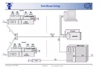
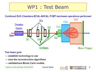
Test Beam Setup Scintillators to define beam trigger (FNAL), Small Scint (1x1 or 2x2cm) to define trigger region (?), Fe Absorber + large Scint to tag Muons (?) Wire Chambers for Beam position measurement (FNAL) Two Cherenkov for e/pi Identification (FNAL) Test module (4x4 modules, 8x8 towers) (WSU) X-Y moveable platform, Rotating (FNAL,WSU,Home Depot) Readout electronics for Beam Counters (FNAL), share with T950 during setup. EMCAL readout and DAQ (ORNL) Facility expertise/contact (Erik Ramberg, FNAL) Shift crew and data analysis team (?)
Preparation Status • 16 Modules from WSU with APD+preamplifiers - soon ready • DAQ - rather than attempting to merge trigger counters into ALICE DAQ we will run to parallel event streams sync’d by event counter to be merged “offline” (“flying blind”: need immediate processing). • ALICE DAQ for PHOS FEE operational • FNAL DAQ operational - but will need to develop code to translate and merge with FEE data. • Weiner CBD-USB - backup solution, same datastream merging problem. • FEE - we have “in hand” and working only 8 channels of readout! • Transition cards and Intermediate PCBs are being shipped from CERN - enough for other 56 channels - will need to assemble IPCB connectors and cables. • Second FEE (v1.1) is so far “Dead”. If it cannot be repaired we will have only 32 channels of readout. A 5x5 array would be “okay”
Preparation Status • Two other known “problems”: • So far have been unable to program FEE firmware • Perhaps not necessary for test since FEE “works” • So far the APD bias software control has not been demonstrated to work - unclear if it should with v1.0 card and firmware we have operational. • Other major task is to confirm shorter shaping time works - (it seems to, see below) and to change half or all FEE channels to use shorter shaping time.
Data-taking and Software Status Using analysis software from PHOS folks; used for studies of their 2004 test beam data. Written by A. V. Kuryakin (Sarov). Modifications by Andre Mischke (Utrecht, CERN, LBNL), incl. plot macros etc. Most significant help from Andre and Hans Mueller in understanding how to take and analyze data! In addition, also valuable help from other PHOS people: Johan Alme, Per Thomas Hille (both from Bergen) and Zhongbao Yin (Wuhan). Note: Report mostly from David Silvermyr (ORNL)
Taking data! Thanks to setup work at CERN (Andre Mischke, Hans Muller, Peter Jacobs) + new RCU firmware version (not yet quite bug-free: miss one channel), we were able to run the DAQ and take data fairly quickly.
DCS/RCU communication + misc. scripts Communication with Readout Control Unit (RCU) via Linux-lite interface. We have developed simple perl scripts to handle channel mapping (Module, CSP, Channel) lookups and generating instructions for APD HV bias control via register interface. Not fully tested yet, and perhaps not too elegant, but should be ok for test beam efforts.
Data Analysis So-called ‘mp-altro’ analysis code from PHOS folks was extremely useful in the first look at data and e.g. figuring out how the 10-bit adc samples were packed in the output, checking trailer words etc.. Also a lot of useful code for e.g. fitting pulse shapes; checking RMS and pedestals,.. Some drawbacks were found though: 1) ~1300 histogram were produced per analysis run (for 32 channels worth of readout – would double for us..) 2) No ntuple-style output. 3) To study shapes for different events require changing hardwired event-number and recompile in between. I.e. not too flexible, and probably problematic to align data with trigger event stream.
First Data LED-pulse; ADC vs sample. Note: 2 ms shaping time, 4 ms peaking time (20 ms fullscale) Pedestal RMS (High Gain) vs Pre-amp number.
Shaping Changes: Scope Traces LED-pulse; Note: 2 ms shaping time, 4 ms peaking time (4 ms/div) LED-pulse; Note: 100 ns shaping time, 200 ns peaking time (4 ms/div)
Shaping Changes: Scope Traces LED-pulse; Note: 2 ms shaping time, 4 ms peaking time (4 ms/div) LED-pulse; Note: 100 ns shaping time, 200 ns peaking time (400 ns/div)
Shaping Changes: Digitized 2 ms shaping.. – not so nice. Narrow shaping (100 ns) • Negative pedestal? (high gain)
Shaping Changes: Digitized Pedestals (Low gain) CSP 30 and 31 with APD @ 300V. CSP 30 with 2 ms shaping, CSP 31 with EMCal shaping (100 ns). (CSP 11 sick?!, CSP 3 Low gain missing due to RCU bug.) • Better RMS with 100ns shaping! • Negative pedestal? (high gain)
Electronic logbook Installed e-log on pcemcal001. This is a lightweight (just ascii), simple and easily configurable logbook (used by PHENIX for a couple of years) that should be adequate to keep track of all setup and test- beam activities. Find/search-function works well.
Software Plan To remedy limitations from existing mp-altro code, we have created a simpler down-scaled version (~ factor 4 less lines of code) of the analysis program that writes a ROOT TTree with all samples for all channels for all events, i.e. no loss of the information we are interested in. Perhaps interestingly,the resulting ROOT file is approx. a factor 4 smaller than the bit-packed DATE file. [A gzip of the DATE file reduces size by factor 6, so ROOT compression is not so bad] This isolates the somewhat complicated unpacking code to a part most will not need to look at, and we will work on making a simple analysis package that most collaborators who are interested can more easily use, and contribute to, with things like pulse shape finding and fitting etc. in a compiled code environment with familiar ROOT ingredients. We’ll pick up components from the existing mp-altro code. This port will be a cut and paste exercise over the next week or so in TN; should be ready well in time before the test beam period starts. Once we get data, some effort will be needed to synch trigger and EMCal data. Should not be hard in principle but we’ll see how it works out in practice.
Cool Result: Test Energy and Position Use p-+C reaction to produce p0 and h With 5 GeV beam at CERN PS (~30p0/ 104p)