Download
1 / 42
420 likes | 609 Views
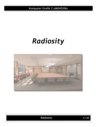
Real-Time Parallel Radiosity. Matt Craighead May 8, 2002 6.338J/18.337J, Course 6 AUP. What is Radiosity?. A computer graphics technique for lighting Two types of lighting algorithms: Local: easy, fast, but not realistic Global: slow, difficult, but highest quality

E N D
Real-Time Parallel Radiosity Matt Craighead May 8, 2002 6.338J/18.337J, Course 6 AUP
What is Radiosity? • A computer graphics technique for lighting • Two types of lighting algorithms: • Local: easy, fast, but not realistic • Global: slow, difficult, but highest quality • Radiosity is a global algorithm • Global algorithms try to take into account interreflections in scenes.
Radiosity in Real Time? • Local algorithms can easily run in real time, either in software or hardware. • Computational demands grow with number of surfaces and number of lights. 106 surfaces is not unreasonable! • Most global algorithms take quadratic time in number of surfaces (all interactions!).
Local Doesn’t Mean Bad Id Software’s Doom 3 (video capture)
…but Global is Better State-of-the-art radiosity rendering from 1988 (5 hours render time!)
Local Lighting Math • Consider a light source at some point in three-dimensional space, and a surface at some other location. • How much does the light directly contribute to the brightness of the surface? • Note that global algorithms still need to do local lighting as a first step.
Local Lighting Math • Set up a 3-dimensional coordinate system centered on the surface. Define unit vectors L (light), N (normal), E (eye): • L points towards the light. • N is perpendicular to the surface. • E points towards the viewer. N E L
Local Lighting Math • If an object sits between the light and surface, the lighting contribution is zero. • Otherwise… • Surfaces generally reflect light in two ways: “diffuse” (dull) and “specular” (shiny). • We can see three colors: red, green, blue. • So let Md, Ms be 3-vectors indicating how much of [R,G,B] are reflected in each way.
Local Lighting Math • Diffuse lighting is independent of view angle. It is brightest when N and L are most closely aligned, and falls off with the cosine of the angle between them. • All lighting also falls off with the square of the distance from the light source. • So, the diffuse term is d-2Md(N · L).
Local Lighting Math • Specular lighting is view-dependent. In one simple formulation (Blinn shading), we determine the vector H halfway between E and L and evaluate d-2Ms(N · H)s, where s indicates the shininess of the surface. H N E L
Local Lighting Math • The easiest way to think of H, the half-angle vector, is that if H and N were aligned, and the surface were a mirror, then the light would reflect straight to the eye. • (N · H)s can be thought of as representing a probability distribution of “microfacets,” whose normals are clustered around N but do vary. Smoother surfaces have higher s.
Local Lighting Math • So, our full contribution from a light source is d-2(Md(N · L) + Ms(N · H)s). • This may also be multiplied by a light color. • We may also add in an emissive term Me for glowing objects. • If the lack of interreflection makes things too dark, we may add an “ambient” term LaMd.
Approximations • We may not compute this formula at every pixel on the screen, but only at the vertices of the object instead. • The specular exponent may be evaluated using a power approximation rather than a real power function. • The specular formula is already a cheesy hack…
More Approximations • Shadows are hard. At the cost of much realism, they can be omitted or faked. • Draw a little dark spot under an object • Ambient is itself an approximation of real global illumination. • N · L and (N · H)s are idealizations—in reality, this can be an arbitrary 4-dimensional function called a “BRDF.”
Radiosity • Radiosity is a global algorithm that handles diffuse lighting only. • The term “global illumination” refers to global algorithms that handle specular lighting also. • Specular makes things much more difficult. • I will only discuss plain radiosity.
Radiosity in a Nutshell • Suppose there are n surfaces in the scene. • Let Ai be the area of surface i. • Let Ei be the amount of light energy emitted from surface i per unit time and area. • Let Bi be the amount of light energy emitted and/or reflected from surface i per unit time and area. • Let i be the diffuse albedo of surface i.
Radiosity in a Nutshell • Now, let Fij (called a “form factor”) be the fraction of light from surface i that reaches surface j. • Then, for all i, we must have: AiBi = AiEi + i j [1,n] AjBjFji • This is just a linear system with n equations and n unknowns. Solve and you get the B’s.
That Easy? • Well, not quite that easy. • Solving the system of equations is O(n3). • So we’ll iterate instead. • We still have to do local lighting. • These become the Ei’s. • We have to compute the Fij terms somehow. • This turns out to be expensive. • If the scene is static, precompute!
Computing Form Factors • Fij turns out to be a big ugly integral over the area of both i and j. • Worse, one of the terms in the integral is whether the two dA’s can see one another! • So, no closed-form solution. • Standard numerical integration is no good. A raycast per sample takes too long.
Computing Form Factors • The usual solution is called the “hemicube algorithm.” • Render the scene from the point of view of the surface, in all directions. In effect, you are projecting onto a hemicube. • Count up the number of times you can see each surface (weighted appropriately). • Takes advantage of 3D acceleration!
Simplified Radiosity Equation • It so happens that FjiAj = FijAi. • This is a simple property of the integral for F. • So we can simplify the radiosity equation: AiBi = AiEi + i j [1,n] AjBjFji AiBi = AiEi + i j [1,n] AiBjFij Bi = Ei + i j [1,n] BjFij B = E + RB (where Rij = iFij)
Solving the Radiosity Equation • B = E + RB is just a matrix/vector equation. • Direct solution: B = (I R)-1E • Iterative solution: • If E is a local lighting solution, then call it B0. • Now let Bi+1 = B0 + RBi. • Then, Bi is simply the lighting solution after i bounces! Since i < 1 for all i (conservation of energy), the Bi’s converge to B.
Iterative vs. Direct Radiosity • If F is a dense matrix, then direct solution takes time O(n3), while k steps of iteration takes time O(kn2). • Realistically, k is just a constant; say, 5. • Iterative solution is practical with n ranging up to the hundreds of thousands! • Iteration time is proportional to the number of nonzero entries of F.
Sparsity of Form Factors • In a simple cube-shaped room, all form factors will be nonzero except for pairs on the same wall. • So F is 5/6 nonzero. Not very encouraging… • As more objects are added, F becomes sparser. • As the scene expands beyond one room, F becomes much sparser. • So iterative radiosity scales extremely well!
Storage and Precision • Radiosity hogs memory. • If you grid a cube-shaped room 100x100 on each wall, and store F as a dense matrix of floats, that’s 14.4 GB. (!!!) • Storing F as sparse helps a lot. • Good for iteration speed too. • Using smaller values than floats helps too. • 16-bit fixed-point is good enough.
RLE Encoding of Form Factors • F tends to have runs of zeros and nonzeros. • Smart traversal order of grids makes the runs longer. Bad Good
RLE Encoding of Form Factors • My disk storage format: • 1 byte: run length, run type • Length up to 84, type is zero, 255, or 65535 • Then, variable # bytes with run data • Compression ratio for my scene: 5.97:1 • My memory storage format: • 2 bytes: run length up to 65535 • 2 bytes: run type (zero or 65535) • 2N bytes: run data • Compression ratio for my scene: 2.49:1
Parallelization • Split up the surfaces among the CPUs. • Each CPU owns those rows of the form factor matrix. • Each CPU computes its surfaces’ local lighting. • Every iteration requires an all-to-all communication, so that each CPU has the full B vector. • At present, my storage of F is unbalanced; compression ranges from 4.3:1 to 1.6:1.
Radiosity Iteration Kernel • Hand-written MMX assembly code (only main inner loop shown): inner_loop: prefetchnta [ebx+128] prefetchnta [eax+128] movq mm4, [eax] pshufw mm7, mm4, 0xFF pshufw mm6, mm4, 0xAA pshufw mm5, mm4, 0x55 pshufw mm4, mm4, 0x00 pmulhuw mm4, [ebx] pmulhuw mm5, [ebx+6] pmulhuw mm6, [ebx+12] pmulhuw mm7, [ebx+18] paddw mm0, mm4 paddw mm1, mm5 paddw mm2, mm6 paddw mm3, mm7 add eax, 8 add ebx, 24 dec esi jnz inner_loop
Radiosity Kernel Performance • Timed 8 CPUs doing 500 iterations. • Portable C fixed-point kernel: 38.04 s • Optimized MMX kernel: 21.64 s • On most loaded CPU, works out to 528 million multiply-adds/s for the C version, 1.24 billion multiply-adds/s for MMX. • But MMX code wastes 25% of them, so real rate is 928 million.
Local Lighting Implementation • One raycast is required for each quad, for each light source! This can be expensive. • To accelerate raycasts, I made a simplified version of my scene that was virtually indistinguishable for raycasting purposes. • 13028 quads reduced to 120 polys, 110 cylinders • Some cylinders used as geometry, some as bounding volumes
Overall Performance • Again, 8 CPUs on 500 iterations: • Iteration only: 21.64 s • Communication only: 5.96 s • Iteration plus communication: 26.84 s • All computation: 65.7 s • All computation plus communication: 64.38 s
Remarks on Performance • The communication overlaps very well with the computation, to the point that it is actually a speedup. (!) • MPI_Isend, MPI_Irecv are essential to achieving this. • The O(n) local lighting computation is actually taking much longer than the O(n2) radiosity computation. • Local lighting is only pseudo-O(n), because of the raycast cost—although for large scenes, raycast cost should still be much less than O(n2), due to other optimizations.
Radiosity Frontend • Separate client application that runs on a Windows PC with OpenGL acceleration. • Radiosity solver running on cluster is server. • Original plan was that the frontend would send the scene to the server, and the server would use the scene provided. • Since the cluster has no OpenGL acceleration, I was reluctantly forced to precompute form factors. • All aspects of scene except form factors still sent to the server by the client; form factors are read from disk.
Client/Server Architecture • User precomputes form factors and FTPs them to the Beowulf. • Server listens on beowulf.lcs.mit.edu:5353. • Client connects and sends scene information. • Server reads form factors off of disk. • Both open a network thread. • Server streams radiosity to client via TCP/IP. • Computation, rendering, and communication are completely decoupled.
Frontend Features • Per-vertex or per-pixel local lighting, with local viewer. Optional specular. • Shadows implemented using stencil buffer. • Display radiosity input/output (E and B). • Bilinear filtering of radiosity solutions on grid-shaped surfaces. • Ultra-high-quality mode where radiosity is used for indirect lighting only.
Work Yet to be Done • More complex scene would be nice. This one is 13K quads, and I should be able to do 50K. • More optimization work on raycasting. • Better load balancing. • Optimization of some modes on frontend, so they run reasonably on my laptop’s GeForce2 Go, not just on a GeForce4 Ti… • Alleviation of ugly banding on certain lighting modes caused by 8-bit-per-component precision.
Conclusions • Real-time radiosity is feasible. • Not tomorrow, but today. • If today’s cluster is tomorrow’s desktop, real-time radiosity could start showing up in real applications not too many years from now. • Biggest limitation may be the ability to compute form factors efficiently. • Faster graphics hardware will make this happen.