Download
1 / 33
340 likes | 1.07k Views
Illustrations of flow nets. 3D6 Environmental Engineering II Dr Gopal Madabhushi. 5m. Trench supported by sheet piles. 6m. 6m. Uniform sand. 6m. Impermeable clay. 5m. Trench supported by sheet piles. 6m. 6m. Uniform sand. 6m. Impermeable clay. 5m. Trench supported by sheet piles.

E N D
Illustrations of flow nets 3D6 Environmental Engineering II Dr Gopal Madabhushi
5m • Trench supported by sheet piles 6m 6m Uniform sand 6m Impermeable clay
5m • Trench supported by sheet piles 6m 6m Uniform sand 6m Impermeable clay
5m • Trench supported by sheet piles 6m h=6m Nh=10 Nf=2.5+2.5 6m Uniform sand 6m Impermeable clay
Steel sheet Water pumped away • Excavation supported by a sheet pile Uniform sand Shale
Steel sheet Water pumped away • Excavation supported by a sheet pile Uniform sand Shale
Steel sheet • Reduced sheet penetration; possible liquefaction v = 0 Uniform sand Shale
Reservoir • Reduced sheet penetration; possible liquefaction v = 0 Tail water Uniform sand Shale
Reservoir • Concrete dam or weir Tail water Uniform sand Shale
Reservoir • Concrete dam with cut-off; reduces uplift pressure Uniform sand Shale
Reservoir • Concrete dam with cut-off; reduces uplift pressure Uniform sand Shale
Elevation Aquifer heads Observation well pumped well • Pumped well in confined aquifer H Radial flow aquifer D Impermeable stratum Plan
Elevation Aquifer heads Observation well pumped well • Pumped well in confined aquifer H Radial flow aquifer D Impermeable stratum Plan
Clay dam, no air entry atmospheric line reservoir drain clay Shale
Clay dam, no air entry atmospheric line reservoir drain clay Shale
Observation well • Clay dam, no air entry atmospheric line reservoir drain clay Shale
Clay dam, no air entry, reduced drain; seepage out of downstream face atmospheric line Not possible reservoir clay Shale
Clay dam, with air entry reservoir drain clay Shale
Clay dam, with air entry reservoir drain clay Shale
Clay dam, no capillary, reduced drain; seepage out of downstream face reservoir clay Shale
Clay dam, no capillary, reduced drain; seepage out of downstream face reservoir clay Shale
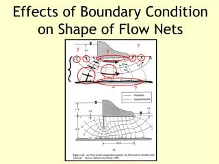
Flow of water in earth dams • The drain in a rolled clay dam will be made of gravel, which has an effectively infinite hydraulic conductivity compared to that of the clay, so far a finite quantity of flow in the drain and a finite area of drain the hydraulic gradient is effectively zero, i.e. the drain is an equipotential
Flow of water in earth dams • The phreatic surface connects points at which the pressure head is zero. Above the phreatic surface the soil is in suction, so we can see how much capillarity is needed for the material to be saturated. If there is insufficient capillarity, we might discard the solution and try again. Alternatively: assume there is zero capillarity, the top water boundary is now atmospheric so along it and the flow net has to be adjusted within an unknown top boundary as the phreatic surface is a flow line if there is no capillarity.
Flow of water in earth dams • If then in the flow net, so once we have the phreatic surface we can put on the starting points of the equipotentials on the phreatic surface directly
Unsteady flow effects • Consolidation of matrix Change in pressure head within the soil due to changes in the boundary water levels may cause soil to deform, especially in compressible clays. The soil may undergo consolidation, a process in which the voids ratio changes over time at a rate determined by the pressure variation and the hydraulic conductivity, which may in turn depend on the voids ratio.
Breakdown of rigid matrix • Liquefaction (tensile failure) The total stress normal to a plane in the soil can be separated into two components, the pore pressure p and the effective inter-granular stress ’: By convention in soils compressive stresses are +ve. Tensile failure occurs when the effective stress is less than the fracture strength ’fracture, and by definition for soil ’fracture=0. When the effective stress falls to zero the soil particles are no longer in contact with each other and the soil acts like a heavy liquid. This phenomenon is called liquefaction, and is responsible to quick sands.
Large upward hydraulic gradients: Uniform soil of unit weight Upward flow of water
standpipe Water table and datum Critical potential Head Critical head Pressure hcrit Uniform soil of unit weight Plug of Base area A z Gap opening as plug rises Upward flow of water
At the base of the rising plug, if there is no side friction: So if v=0 then v = p and : , icrit=0.8~1.0
where icrit is the critical hydraulic gradient for the quick sand Condition. As 18~20 kN/m3 for many soils (especially sands and silts) and w 10 kN/m3 :
Frictional (shear failure) • Sliding failure of a gravity concrete dam due to insufficient friction along the base:
Reservoir Tail water W H1 H2 W´ Uniform sand
Limiting condition on shear force T is: where tan’max is the co-efficient of friction, so considering the base of the dam we are looking for: where W‘ = W-U is the effective weight of the dam, U is the total uplift due to the pore pressure distribution p along the base of the dam, and F = H1- H2 is the shear force along the Dam base