Download

1 / 30
300 likes | 408 Views
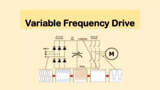
Variable Frequency AC Source. Students: Kevin Lemke Matthew Pasternak Advisor: Steven D. Gutschlag. Outline. Summary Patents and Standards Functional Description and Complete System Block Diagram Functional Requirements List and Performance Specifications Lab Work

E N D
Variable Frequency AC Source Students: Kevin Lemke Matthew Pasternak Advisor: Steven D. Gutschlag
Outline • Summary • Patents and Standards • Functional Description and Complete System Block Diagram • Functional Requirements List and Performance Specifications • Lab Work • Equipment & Parts List • Schedule
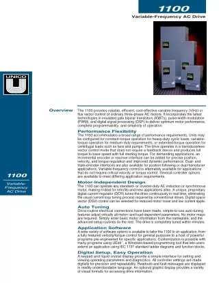
Project Summary • Variable Frequency AC Source (VFACS) • Capable of delivering 208 Vrms and 5 A (35.5V rms for initial testing) • Frequency range from 0 to 60 Hz
Patents & Standards • UL-61800-5-1 Safety Requirements for AC Drives • NEC, NFPA 70E National Electric Code • IEEE-519-1992 Harmonic Control
PWM Generation Controller • Produces PWM signals for the Gate Drive Circuitry • Use a LabVIEW based cDAQ controller from National Instruments • Able to control both single phase and three phase systems
PWM Generation Controller • Produce TTL level PWM signals • Produce waveforms representative of sine waves from 0-60 Hz • Produce waveforms following proper V/Hz ratio of 0.5892
Gate Drive Circuitry • High speed signal isolator and driver • Use optical isolators and gate driver chips to isolate and amplify signal to the Inverter • Optical isolators and gate drivers chosen for speed and robustness
Gate Drive Circuitry • Along with inverter, capable of switching at 1% duty cycle of 15 kHz switching frequency without clipping • Optical Isolator • 6N137 Optocoupler • Isolate cDAQ outputs from Inverter, Filter, and Load • Gate Driver • IR-2110 • Amplify PWM from TTL to +15V 2A level adequate for driving the Inverter
Inverter • PWM Signal Amplifier for AC machine application • Use IGBT pairs and DC rails to amplify PWM signal • IGBTs used for high voltage capabilities and availability • Single- and three-phase configurations
Inverter • Single-phase Inverter • Fairchild FMG2G75US60 IGBT Pair • Each IGBT will receive one PWM signal • Output one dual-sided PWM signal representing the necessary sine wave • Have 0 and 100 VDC rails capable of providing 15 A • Three-phase Inverter • Three single-phase inverters • Single-phase inputs 120⁰ out of phase from any other input • Capable of 5 A per phase
Filter • Used to extract sine wave encoded in PWM signal • Three identical filters used (one for each phase) • LC filter
Filter • LC Filter • Components rated for 400V and 15A • Output sinusoidal waveform extracted from PWM signal
Load • Overall system output used for testing • Initially resistive-inductive (RL) for both single- and three-phase systems • Final tests will be performed on a three-phase motor • Shall be able to draw the rated power from the system
Lab Work • Volts/Hertz Ratio Testing • Simulink Model of controller • 0 to 60 Hz
Equipment & Parts List • LabVIEW Student Edition • NI-cDAQ-9174 Data Acquisition Chassis • NI-9401 Digital I/O • NI-9221 Analog-to-Digital Converter • NI-9211 Thermal Couple • IR 2110 Gate Driver • 6N137 Optical Isolator • FMG2G75US60 IGBT Pair with anti-parallel diodes • Sources and Scopes available in Power Lab
Schedule • Remaining Fall Semester – Exposure to LabVIEW environment • 1/27/2013 -LabVIEW Tutorials • 2/3/2013 -Build & test single phase optical isolator/build single phase gate driver & inverter • 2/10/2013 -Finish & test single phase gate driver & inverter • 2/17/2013 -Basic LabVIEW controller design • 2/24/2013 -Build & test three phase optical isolator/build three phase gate driver & inverter • 3/3/2013 -Finish & test three phase gate driver & inverter
Schedule • 3/10/2013 -LC filter & three phase resistive load design • 3/17/2013 -Build and test LC filter & three phase resistive load • 3/24/2013 -Testing with three phase AC machine • 3/31/2013 -Controller tuning • 4/7/2013 -Source conversion design • 4/14/2013 -Source conversion building and testing • 4/21/2013 -Final system testing and analysis
Datasheets • http://www.fairchildsemi.com/ds/6N/6N137.pdf • http://www.daedalus.ei.tum.de/attachments/article/257/IR2110_IR2110S_IR2113_IR2113S.pdf • http://pdf.datasheetcatalog.com/datasheet/fairchild/FMG2G75US60.pdf