Download
1 / 23
230 likes | 427 Views
Five Key Computer Components. Central Processing Unit Memory Input/Output (I/O) Devices Disk Storage Programs. Central Processing Unit . Executes instructions (programs) To do this the CPU can: read/write information in memory recognize difference between instruction and data

E N D
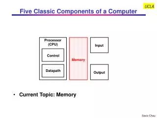
Five Key Computer Components • Central Processing Unit • Memory • Input/Output (I/O) Devices • Disk Storage • Programs
Central Processing Unit • Executes instructions (programs) • To do this the CPU can: • read/write information in memory • recognize difference between instruction and data • control I/O devices
Memory • Also known as Primary Storage • Provides temporary storage of programs and data • Can be accessed directly by CPU or through I/O devices
Input/Output Devices • Mouse • Keyboard • Video Display • Printer • Modem • Communication Lines (Networks)
Disk Storage • Also known as secondary storage • Provides permanent (non-volatile) storage of programs or data.
Programs • System Software • BIOS- Basis Input/Output Services (ROM) • Operating System - DOS, Windows, Unix • Application Software • Word Processors • Database • etc
More PC Hardware Terms • serial - all information goes one bit at a time over the same wire. • parallel - bits go over many wires running side by side. • clock - sends pulses to synchronize the CPU and other hardware. • MHz - megahertz, one million clock pulses per second.
Main Hardware Components • System Unit • Display • Keyboard • Mouse
System Unit • System Board (Mother board) • Central Processing Unit (CPU) • Memory (RAM - Random Access Memory) • ROM (Read-only Memory) • Expansion Slots • Math Co-processor • 486 and 586 CPU has integrated Math co-processor.
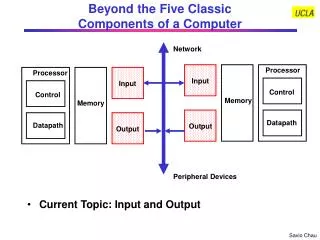
PC Expansion Bus • Connects CPU to circuit boards which control devices such as disk drives, printer, display, modems, etc
ISA: Industry Standard Arch. • Commonly known as AT bus. • 8 or 16 bit data bus, 98-pin expansion connector. • Can access up to 16 MB of memory. • Common and cheap but very slow (8Mhz).
MCA • Micro Channel Architecture • Designed by IBM to replace ISA in PS/2 system. • not compatible with ISA bus boards. • 16 and 32 bit versions. • Not seen much anymore.
EISA • Extended Industry Standard Architecture • designed by Compaq and other clone companies as alternative to MCA • Allows use of ISA bus boards in new computers.
Local Bus • Communicates at system speed • Memory, display, disk drives all can use local bus. • Provides 32 or 64 bit data access.
Local Bus Standards • VESA VL Bus - (Video Electronics Standards Association) • First to gain popularity • 32 bit bus running at 33 MHz can handle up to 107 Mbytes/second • PCI (Peripheral Component Interconnect) • 32 bit bus running at 33 MHz can handle up to 132 Mbytes/second • faster and more easily expanded than VESA bus
SCSI • pronounced “scuzzy” • used with printers, hard disks, tape drives. • excellent for high-speed data transfer in multi-user systems or file servers. • Can handle up to 7 devices on one adaptor card.
Gates • Fundamental building block of all digital logic circuits. • Logic functions are implemented by the interconnection of gates. • An electronic circuit that produces an output signal that is a simple Boolean operation on the input signals. • The basic gates are: AND, OR, NOT, NAND, NOR. • Basic gates have either one or two input lines and a single output line. • When the signals on the input lines change, the correct output signal is generated by the gate, almost simultaneously, delayed only by the propagation time of the signals through the gate (called gate delay).
Multiplexers • A multiplexer connects multiple inputs to a single output. At any given time, one of the inputs is selected and is passed directly to the output. Multiplexers are used in digital circuits to control signal and data routing. Shown below is a block diagram of a 4-to-1 multiplexer. There are four input lines labeled D0, D1, D2, and D3 of which one is selected to provide the output signal F. To select one of the four input signals, a 2-bit selection code is required and this is implemented as the two select lines labeled S1, and S2.
Decoders • A decoder is a combinational circuit which has a number of output lines, of which only one is valid (asserted) at any time, dependent upon the pattern on the input lines. In general, a decoder has n input lines and 2n output lines. Decoders are heavily used in digital computers for address decoding.