Download
1 / 34
340 likes | 461 Views
Jonathan C.L. Liu, Ph.D. Department of Computer, Information Science and Engineering (CISE), University of Florida. Quick Review on Data Link Layer – Part 2. Selected wireless link standards. Outdoor 50 – 200m. Mid range outdoor 200m – 4km. Long range outdoor 5km – 20km. Indoor

E N D
Jonathan C.L. Liu, Ph.D. Department of Computer, Information Science and Engineering (CISE), University of Florida Quick Review on Data Link Layer – Part 2
Selected wireless link standards Outdoor 50 – 200m Mid range outdoor 200m – 4km Long range outdoor 5km – 20km Indoor 10 – 30m 54 Mbps 802.11{a,g} 5-11 Mbps .11 p-to-p link 802.11b 1 Mbps 802.15 3G 384 Kbps UMTS/WCDMA, CDMA2000 2G 56 Kbps IS-95 CDMA, GSM
MSC • connects cells to wide area net • manages call setup (more later!) • handles mobility (more later!) cell • covers geographical region • base station (BS) analogous to 802.11 AP • mobile users attach to network through BS • air-interface: physical and link layer protocol between mobile and BS Mobile Switching Center Public telephone network, and Internet Mobile Switching Center wired network Cellular network architecture
Cellular networks: the first hop Two techniques for sharing mobile-to-BS radio spectrum combined FDMA/TDMA: divide spectrum in frequency channels, divide each channel into time slots CDMA: code division multiple access time slots frequency bands
Cellular standards: brief survey 2G systems: mainly designed for the voice channels only IS-136 TDMA: combined FDMA/TDMA (north america) GSM (global system for mobile communications): combined FDMA/TDMA most widely deployed IS-95 CDMA: code division multiple access
Cellular standards: brief survey 2.5 G systems: voice and data channels for those who can’t wait for 3G service general packet radio service (GPRS) evolved from GSM data sent on multiple channels (if available) enhanced data rates for global evolution (EDGE) also evolved from GSM, using enhanced modulation Date rates up to 384K CDMA-2000 (phase 1) data rates up to 144K evolved from IS-95
Cellular standards: brief survey 3G systems: voice/data/video? Universal Mobile Telecommunications Service (UMTS) GSM next step, but using CDMA CDMA-2000 Targets for the TRUE integration of multimedia communication A design challenge to provide the seamless switching between multimedia applications
Code Division Multiple Access used in several wireless broadcast channels (cellular, satellite, etc) standards unique “code” assigned to each user; i.e., code set partitioning all users share same frequency, but each user has own “chipping” sequence (i.e., code) to encode data encoded signal = (original data) X (chipping sequence) decoding: inner-product of encoded signal and chipping sequence allows multiple users to “coexist” and transmit simultaneously with minimal interference (if codes are “orthogonal”)
CDMA Encode/Decode d0 = 1 1 1 1 1 1 1 1 1 d1 = -1 - - - - 1 - - - - 1 1 1 1 1 1 1 1 1 1 1 1 1 1 1 - - - - 1 1 1 1 - - - - 1 1 1 1 M Di = Zi,m.cm m=1 M 1 1 1 1 1 1 1 1 d0 = 1 - - - - 1 - - - - 1 1 1 1 1 1 1 d1 = -1 1 1 1 1 1 1 1 1 - - - - 1 1 1 1 - - - - 1 1 1 1 channel output Zi,m Zi,m= di.cm data bits sender slot 0 channel output slot 1 channel output code slot 1 slot 0 received input slot 0 channel output slot 1 channel output code receiver slot 1 slot 0
WCDMA Networks Spread the radio signal over a wide fraquency range by modulating it with a code word unique to the user Users can transmit any time using the whole spectrum Receiver distinguishes sender’s signal from other signals by examining the wide spectrum band with a time synchronized duplicate of the spreading code The transmitted signal is recovered by a despreading process at the receiver
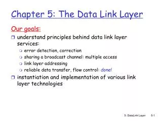
Broadband Wireless The 802.16 Protocol Stack The 802.16 Physical Layer The 802.16 MAC Sublayer Protocol The 802.16 Frame Structure
The 802.16 Physical Layer The 802.16 transmission environment.
The 802.16 Physical Layer (2) Frames and time slots for time division multiplexing.
802.16 MAC Sublayer Protocol Service Classes Constant bit rate service Real-time variable bit rate service Non-real-time variable bit rate service Best efforts service
802.16 Frame Structure (a) A generic frame. (b) A bandwidth request frame.
Bluetooth Bluetooth Architecture Bluetooth Applications The Bluetooth Protocol Stack The Bluetooth Radio Layer The Bluetooth Baseband Layer The Bluetooth L2CAP Layer The Bluetooth Frame Structure
less than 10 m diameter replacement for cables (mouse, keyboard, headphones) ad hoc: no infrastructure master/slaves: slaves request permission to send (to master) master grants requests 802.15: evolved from Bluetooth specification 2.4-2.5 GHz radio band up to 721 kbps P S P M P S S P Master device Slave device Parked device (inactive) M S P 802.15: personal area network radius of coverage
Bluetooth Applications The Bluetooth profiles.
The Bluetooth Protocol Stack The 802.15 version of the Bluetooth protocol architecture.
The Bluetooth Frame Structure A typical Bluetooth data frame.
IEEE 802.15.3 - Overview High data rate WPAN Potential future standard Motivation: The need for higher bandwidths currently supported with 802.15.1 100 Mpbs within 10 meter 400 Mpbs within 5 meter Data, High quality TV, Home cinema
IEEE 802.15.3 - Overview Dynamic topology Mobile devices often join and leave the piconet Short connection times High spatial capacity Multiple Power Management modes Secure Network
IEEE 802.15.3 - Overview Based on piconets Data Devices (DEV) establish peer-to-peer communication Includes also a Piconet Coordinator (PNC)
IEEE 802.15.3 - Beacon Beacon Control information Allocates GTS Synchronization
IEEE 802.15.3 - CAP CAP Allows contention via CSMA/CA Command exchange between DEV and PNC File transfers from DEV without request
IEEE 802.15.3 - CFP CFP Time slot allocation specified in the beacon Reserved bandwidth for DEV MTS: Command, GTS: Data
IEEE 802.15.3 - GTS GTS reservation DEV sends a Channel Time Request (CTR) to PNC Isochronous data: number and duration of slot(s) Asynchronous data: Total amount of data PNC allocates GTSs to DEV via CTA DEV is responsible of utilizing allocated GTSs
IEEE 802.15.3 - GTS Two types of GTSs Dynamic GTS Location within a superframe may change PNC can optimize channel utilization Pseudostatic GTS Only for isochronous data Fixed location within a superframe May be changed, but only after a series of notitications to the DEV
IEEE 802.15.3 Starting a piconet DEV scans the for the best channel and sends out beacons -> the DEV becomes PNC If no channels available: Establishes a child or neighbor piconet instead Requests a private GTS from parent PNC All communication takes place within assigned GTS