Download
1 / 105
1.07k likes | 1.17k Views
The Data Link Layer. Chapter 3. Data Link Layer. Algorithms for achieving reliable, efficient communication between two adjacent machines.

E N D
The Data Link Layer Chapter 3
Data Link Layer • Algorithms for achieving reliable, efficient communication between two adjacent machines. • Adjacent means two machines are physically connected by a communication channel that acts like a wire (bits are delivered in exactly the same order in which they are sent)
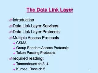
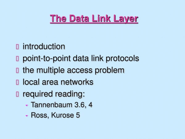
Data Link Layer Design Issues • Services Provided to the Network Layer • Framing • Error Control • Flow Control
Functions of the Data Link Layer • Provide service interface to the network layer • Dealing with transmission errors • Regulating data flow • Slow receivers not swamped by fast senders • Error control and flow control are also found in transport and other protocols • No matter where they are found, the principles are pretty much the same
Functions of the Data Link Layer (2) Relationship between packets and frames.
Services Provided to Network Layer (a) The principal service is transferring data from the network layer on the source machine to the network layer on the destination machine. (a) Virtual communication. (b) Actual communication.
Services Provided to the Network Layer • Unacknowledged Connectionless Service • Acknowledged Connectionless Service • Acknowledged Connection-oriented Service (Three phases) · Connection establishment · data transfer · disconnection
Services to Network layer (1) • Unacknowledged connectionless service • No connection required and without acknowledgement for data frames • Appropriate for low error rate and real-time traffic • Error recovery is up to higher layer
Services to Network layer (2) • Acknowledged connectionless service • No connection required but each frame is individually acknowledged • The sender knows whether a frame has arrived correctly • If it has not arrived within a specified time interval, it can be sent again • Useful for unreliable channel, such as wireless systems. • If bit error rate of the channel is high, this method gets faster packet transmission • A lost acknowledgement causes a packet to be sent several times and thus received several times. • Transport layer may do message recovery but is more expensive than frame recovery at data link layer
Services to Network layer (3) • Acknowledged connection-oriented service • Guarantee error-free and in sequence delivery of data frames • Consists of three phases • Connection set up (variables and buffers initialization) • Data frame transmission • Connection termination (free of variable and buffers)
Services Provided to Network Layer (2) Placement of the data link protocol. • EX: a WAN subnet consisting of routers connected by point-to-point leased telephone lines • The routing code frequently wants the job done right, that is, with reliable, sequenced connections on each of the point-to-point lines • The data link protocol makes unreliable communication lines look perfect
Framing • In the physical layer the bit stream is not guaranteed to be error free • The number of bits received may be less than, equal to, or more than the number of bits transmitted • The data link layer needs to detect and, if necessary, correct errors • The usual approach is for the data link layer to break bit stream from physical layer into frames and compute the checksum for each frame Four framing methods • Character count • Flag bytes with byte (character) stuffing • Starting and ending flags, with bit stuffing • Physical layer coding violations
Framing Approaches - Character Count • Indicate the frame boundary by frame length • The first field in the header specifies the number of characters in the frame • Once an error, frame boundary cannot be recognized and thus recovery is impossible. A character stream. (a) Without errors. (b) With one error.
Framing Approaches –Flag byes with byte stuffing • Delimit the frame by flag bytes • Prevent frame boundary from appearing at the data content by character stuffing. • Character Stuffing: inserting ESC ahead of accidental flag byte within the data content. (a) A frame delimited by flag bytes. (b) Four examples of byte sequences before and after stuffing.
Framing Approaches (3) Starting and ending flags, with bit stuffing • Begin and end with a flag byte “01111110” • Prevent a flag from appearing in data by bit stuffing. • Bit stuffing: inserting 0 after five continuous bit “1” data appear.
Framing Approaches (3) 6 consecutive 1’s 5 consecutive “1” + 1 “0” Bit stuffing (a) The original data. (b) The data as they appear on the line. (c) The data as they are stored in receiver’s memory after destuffing.
Framing Approaches (4) Physical Layer Coding Violations. • Used when physical layer encoding contains redundancy • Example: 01 (H), 10 (L) then 00 or 11 can be used to delimit a frame. Note: One or more combination of the approaches may be used to provide extra protection for framing.
1 0 0 0 violation violation Neutral versus bipolar bit streams. (a) Alternate 1’s and 0’s transmitted in a neutral mode. (b) Equivalent in a bipolar mode. (c) Framing by coding violation.
Error Controlhow to make sure all frames are eventually delivered to the network layer at the destination and in the proper order • Need mechanisms such as • Acknowledgement or NACK • Timer • Retransmission • Sequence numbering Ack Timer Retransmission Sequence numbering
Flow Control • When receiver processes frames slower than the sender, congestion occurs. • Needs some feedback to prevent sender from sending faster than the receiver can process. • Feedback-based flow control • Rate-based flow control
Error Detection and Correction • Error-Correcting Codes • Error-Detecting Codes
Data Redundant
Error Correcting Code • Codeword = Data + Check-bit • n-bit codeword = m data bit + r check-bit • 2m out of 2n are legal • Hamming distance = The minimum number of bit positions in which two codewords differ. • H = d+1 --> detect d errors; • H = 2d+1 --> correct d errors.
Error-Correcting Codes • Parity bit: • detect single bit error and H = 2. • Example of H = 5 d = (5-1)/2 = 2 • 0000000000 • 0000011111 • 1111100000 • 1111111111 • 0000000111 ==> two bit errors in 0000011111 • 0000000011 ==> three bit errors in 0000011111 but be corrected to be 0000000000 Out of Correcting Capability
Error Correcting Codes • Correcting single bit error of n-bit codeword requires (m + r + 1) < 2r (lower bound for r) • n + 1 bit patterns dedicated to one codeword ==> (n+1)2m< 2n and n = m + r n Each 2m legal message requires n+1 bit patterns dedicated to it. N possible bit patterns at a distance 1 from it
Hamming code • Achieve lower bound of r • The codeword is numbered consecutively starting from left end as 1. • The bits of powers of 2 (1,2,4,8,…) are check bits; the rest (3,5,7, …) are filled with m data bits. • A check bit forces the parity of some collection of bits, including itself, to be even (or odd).
Hamming Code (2) • A bit is checked by just those check bits occurring in its expansion (e.g., bit 11 is checked by bits 1,2, and 8) • Checking algorithm • Initialize counter == 0 • Examine all check bits • If check bit k is error, add k into the counter. • After all check bits are checked, the counter contains the number of the incorrect bit.
ASCII 1100001 1 2 3 4 5 6 7 8 9 10 11 Transmitting 1 0 1 1 1 0 0 1 0 0 1 Bit 1 0 0 0 1 2 0 0 0 0 3 0 0 1 1 4 0 1 0 0 5 0 1 0 1 6 0 0 0 0 7 0 0 0 0 8 1 0 0 0 9 0 0 0 0 10 0 0 0 0 11 1 0 1 1 0 0 0 0 If received 1 1 1 1 1 0 0 1 0 0 1
error If error occurs 0 0 0 1 0 0 1 0 0 0 1 1 0 1 0 0 0 1 0 1 0 0 0 0 0 0 0 0 1 0 0 0 0 0 0 0 0 0 0 0 1 0 1 1 0 0 1 0 Error in second bit!
漢明碼 • 漢明碼設計上兼具錯誤檢查及錯誤更正功能。 • 對於n位元的資料,在加入 個位元檢查碼後,總傳輸位元數達到位元。
漢明碼 • 舉例來說,如果第9位元在傳送過程發生錯誤,由“0”變成“1”。 • 這就道出是第(1001)2=9位元出錯! • 所以接收端自行將"1"改正成"0"。
Error-Correcting Codes Use of a Hamming code to correct burst errors.
Error Detecting Code • Parity code • detect single or odd # of bit errors • detect burst error of n-bit by matrix checksum on each column of n-bit wide and h-bit high data and put the checksum at the h+1 row. • Cyclic redundancy code • Polynomial code • Using Exclusive OR in addition and subtraction.
Two-dimension parity checks 1 0 0 1 0 0 0 1 0 0 0 1 1 0 0 1 0 0 1 1 0 1 1 0 1 0 0 1 1 1 • Several information rows • Last column: check bits for rows • Last row: check bits for columns Can detect one, two, three errors, But not all four errors. 1 0 0 1 0 0 0 0 0 0 0 1 1 0 0 1 0 0 1 1 0 1 1 0 1 0 0 1 1 1 1 0 0 1 0 0 0 0 0 0 0 1 1 0 0 1 0 0 1 0 0 1 1 0 1 0 0 1 1 1 1 0 0 1 0 0 0 0 0 1 0 1 1 0 0 1 0 0 1 0 0 1 1 0 1 0 0 1 1 1 1 0 0 1 0 0 0 0 0 1 0 1 1 0 0 1 0 0 1 0 0 0 1 0 1 0 0 1 1 1 2 errors 3 errors 4 errors 1 error
Cyclic redundancy code • Polynomial code • Using Exclusive OR in addition and subtraction.
CRC Algorithm • Shift M(x) left by r bits (r is the degree of G(x)). • Divide xrM(x) by G(x) • Subtract xrM(x) by the remainder in last step to obtain the checksumed frame to be transmitted, T(x). • T(x) is divisible by G(x)
CRC Error Check • Receive T’(x) • Divide T’(x)/G(x) • if no remainder, the frame is accepted • if yes, error is found. • T’(x) = T(x) + E(x) • T’(x)/G(x) = T(x)/G(x) + E(x)/G(x) = E(x)/G(x)
Error-Detecting Codes Calculation of the polynomial code checksum. Message Checksum
Example of CRC encoding x3 + x2 + x 1110 x3 + x+ 1 x6 + x5 1011 ) 1100000 x6 + x4 + x3 1011 x5 + x4 + x3 1110 1011 x5 + x3 + x2 1010 x4 + x2 1011 x4 + x2 + x x 010 • Transmitted codeword: • b(x) = x6 + x5 + x • b= (1,1,0,0,0,1,0) • Generator polynomial: g(x)= x3 + x + 1 1011 • Information: (1,1,0,0) i(x) = x3 + x2 • Encoding: x3i(x) = x6 + x5
Error Detection of CRC • Single bit error: E(x) = xi • Not divisible by G(x) if G(x) has more than one term. • Double bit Error: E(x) = xi + xj = xj(xi-j +1) • Low degree polynomials the give protection to long frames are known. • E.g., will not divide for any k < 32768 • Odd # of bits in Error: • No polynomial with odd No. of terms contain a factor of (x+1) • if G(x) contain (x+1), indivisible for any odd No. of errors.
Error Detection of CRC (2) • Detect all errors of length < r, if the degree of G(x) is r. • Undetectable error of r+1 bit (the first and the last of the r+1 bits must be 1) with prob. 1/2(r-1) (r+1-2 intermediate bits) • Undetected error of longer than r+1 bits with prob. 1/2r • Example of G(x) • CRC-12 = x12+x11+x3+x2+x1+1
ith position L error pattern d(x) • Error bursts of length L: 0…0110• • • •0001011000 e(x) = xi d(x) where deg(d(x)) = L-1 g(x) has degree n-k; g(x) cannot divide d(x) if deg(g(x))> deg(d(x)) • L = (n-k) or less: all will be detected • L = (n-k+1): deg(d(x)) = deg(g(x)) i.e. d(x) = g(x) is the only undetectable error pattern, fraction of bursts which are undetectable = 1/2L-2 (the first and last bit in L range must be one, the left L-2 bits must match with the coefficients in g(x)). • L > (n-k+1): fraction of bursts which are undetectable = 1/2n-k
Typical standard CRC polynomials • CRC-8: x8 + x2 + x + 1 ATM header error check • CRC-16: x16+x12+x5+1 HDLC, XMODEM, V.41 • CRC-32: x32+x26+x23+x22+ IEEE 802, DoD, V.41, x16+x12+x11+x10+ AAL5 x8+x7+x5+x4+x2+x+1
Characteristics of data link layer/transport layer Data Link layer Transport layer PDUs along the same path? Not really YES PDUs arrive in order? YES if no error occur Not sure How long it take? Determined by the geographical distance Do not know Arrive at all? Generally YES, unless link broken Not guarantee
Service models • Connection-oriented and connectionless • Confirmed and unconfirmed • A service may transfer in constant bit rate ( CBR) or variant bit rate (VBR) • Quality of Service (QoS) • Level of reliability in probability of error, lost, incorrect delivery • Transfer delay (fixed, maximum) • Jitter: the variation of delay
ACK/NAK 1 2 3 4 5 Data Data Data Data End-to-end Data are ACK or NAK by the other end Hop-by-hop Data are ACK or NAK by each hop Data Data Data Data 1 2 3 4 5 ACK/NAK ACK/NAK ACK/NAK ACK/NAK Adaptation functions may be implemented end-to-end or hop-by-hop Figure 5.7
End-to-end versus hop-by-hop • Hop-by-hop: faster recovery & more reliable • but more burden on middle nodes • End-to-end: simpler and only at end-system • QUESTIONS: • could hop-to-hop waivers end-to-end? • NO. it is difficult for all elements in the hop-by-hop • chain to operate correctly, furthermore the errors • may be introduced in middle nodes --Adaptations are implemented at which layer(s)? Data link & network layer Hop-by-hop: End-by-End: Transport & application layer
End-to-end versus hop-by-hop (cont.) • In case of error-detection and recovery: • If frequent errors, use hop-by-hop , otherwise end-to-end • Flow control and congestion control could be exercised on a hop-by-hop or end-to-end basis • Security issue: may be hop-by-hop or end-by-end • IPSec (IP security protocol) in Internet layer, hop-by-hop • SSL (Secure Socket Layer) in transport layer, end-to-end • SSH (Secure Shell) in application layer, end-to-end