Download

1 / 37
420 likes | 485 Views
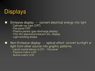
Seven Segment Displays. Digital Electronics. Seven Segment Displays. This presentation will demonstrate how… A seven-segment display can be used to display the decimal numbers 0-9 and some alpha characters. Seven Segment Displays. This presentation will demonstrate how…

E N D
Seven Segment Displays Digital Electronics
Seven Segment Displays This presentation will demonstrate how… A seven-segment display can be used to display the decimal numbers 0-9 and some alpha characters.
Seven Segment Displays This presentation will demonstrate how… A common anode 7-segment display works. A common cathode 7-segment display works.
Seven Segment Displays This presentation will demonstrate how… To select the resistorvalue for a 7-segment display.
Segment Identification A Seven-Segment Display (SSD) is simply a figure eight grouping of LEDs (some include a decimal point or DP). a Each Segment is labeled (a) thru (g). f b g c e d dp
Segment Identification SSDs are available in two configurations: Common Cathode (all LED cathodes are connected) Common Anode (all LED anodes are connected) a f b g c e d dp
SSD Display Possibilities Decimal Digits 0-9
SSD Display Possibilities Select Alpha Characters
SSD Display Possibilities Simple Messages
Basic LED Operations To Turn an LED ON . . . • The ANODE must be at a higher voltage potential (1.5v) than the CATHODE. • The amount of current flowing through the LED will determine the brightness of the LED. • The amount of current is controlled by a seriesresistor. (not shown) To understand how a seven-segment display works, we must review how an LED works. (+) ANODE CATHODE (‒) ←Current Flow
LED Configuration – Anode @ 5 Volts Switch @ 5v LED Off Common Anode Configuration 5v = Off 0v = On
LED Configuration – Anode @ 5 Volts Switch @ 0v LED ON, ANODE @ 5V CATHODE @ 0V (nearly) The 220 resistor controls the current. A larger resistor = less current = dim LED A smaller resistor = more current = brighter LED Common Anode Configuration 5v = Off 0v = On
Example #1: Common Anode SSD • What value would be displayed in the common anode seven-segment display shown?
Example #1: Common Anode SSD • What value would be displayed in the common anode seven-segment display shown? • Solution: • Common Anode: • 0 volts = Segments On: b, c, f, & g • 5 volts = Segment Off: a, d, & e • What number is displayed?
Example #1: Common Anode SSD • What value would be displayed in the common anode seven-segment display shown? a g f b c e d
Example #2: Common Cathode SSD • What value would be displayed in the common cathode seven-segment display shown?
Example #2: Common Cathode SSD • Common Cathode: • 5 volts = Segment On: a, b, d, e, & g • 0 volts = Segment Off: • c & f
Example #2: Common Cathode SSD a g f b c e d
Resistor Values for SSD The resistor value determines the amount of current that is flowing through the LED in the SSD (Seven Segment Display). This is why they are sometimes called currentlimiting resistors. The amount of current determines how luminous (bright) the LED will be.
Resistor Values for SSD If the resistor is too large, the current will be too small and the LED will not be visible. If the resistor is too small, the current will be too large and the LED will be damaged. So, how do you select the correct value? You must readthedatasheet for the SSD that you are using!
A Review of Circuit Theory The diagram below is a single segment of a common anode seven-segment display. The voltage across the LED (when on) is 1.5 volts. ← I
A Review of Circuit Theory Using Kirchhoff's Voltage Law, we know that the voltage across the resistor is 3.5 volts(5v – 1.5v = 3.5v). Then, using Ohm’s Law, we can calculate the value of the resistor if we know the current that is to flow through the LED. ← I
Selecting A Resistor Value Let’s arbitrarily pick a luminous intensity of 1.5 (not too bright, not too dim). From the graph, we need a current of 15mA. LTS-4801JR Common Anode Seven-Segment Display Luminous Intensity vs. Forward Current Graph
Selecting A Resistor Value LTS-4801JR Common Anode Seven-Segment Display Luminous Intensity vs. Forward Current Graph Apply Ohm’s Law Resistance = Voltage/Current R = V ÷ I
Selecting A Resistor Value LTS-4801JR Common Anode Seven-Segment Display Luminous Intensity vs. Forward Current Graph Apply Ohm’s Law Resistance = Voltage/Current R = V ÷ I Voltage = 3.5 V Current = 15 ma
Selecting A Resistor Value LTS-4801JR Common Anode Seven-Segment Display Luminous Intensity vs. Forward Current Graph Apply Ohm’s Law Resistance = Voltage/Current R = V ÷ I R = 3.5 V ÷ 15 ma (R = 3.5 V ÷ .015 A)
Selecting A Resistor Value LTS-4801JR Common Anode Seven-Segment Display Luminous Intensity vs. Forward Current Graph Apply Ohm’s Law Resistance = Voltage/Current R = V ÷ I R = 3.5 V ÷ 15 ma (R = 3.5 V ÷ .015 A ) R = 233 Ω (ohms)
Selecting A Resistor Value LTS-4801JR Common Anode Seven-Segment Display Luminous Intensity vs. Forward Current Graph Nearest actual resistor value to 233 ohms: 220 Ω (ohms)
Example #3: Resistor Value • Calculate the resistor value required to have a luminous intensity of 2.5.
Example #3: Resistor Value • Calculate the resistor value required to have a luminous intensity of 2.5. • Solution: • From the graph, we need a current of ?
Example #3: Resistor Value • Calculate the resistor value required to have a luminous intensity of 2.5. • Solution: • From the graph, we need a current of ?
Example #3: Resistor Value • Calculate the resistor value required to have a luminous intensity of 2.5. • Solution: • From the graph, we need a current of 25mA.
Example #3: Resistor Value • Calculate the resistor value required to have a luminous intensity of 2.5. • Solution: • Using Ohm’s Law, (R = V ÷ I)find resistor value:
Example #3: Resistor Value • Calculate the resistor value required to have a luminous intensity of 2.5. Using Ohm’s Law: R = V ÷ I R = 3.5 V ÷ 25 ma
Example #3: Resistor Value • Calculate the resistor value required to have a luminous intensity of 2.5. Using Ohm’s Law: R = V ÷ I R = 3.5 V ÷ 25 ma R = 3.5 V ÷ .025A
Example #3: Resistor Value • Calculate the resistor value required to have a luminous intensity of 2.5. Using Ohm’s Law: R = V ÷ I R = 3.5 V ÷ 25 ma R = 3.5 V ÷ .025A Resistance = 140 Ω
Example #3: Resistor Value • Calculate the resistor value required to have a luminous intensity of 2.5. Using Ohm’s Law: R = V ÷ I R = 3.5 V ÷ 25 ma R = 3.5 V ÷ .025A Closest standard value: 150 Ω