Download
1 / 26
260 likes | 411 Views
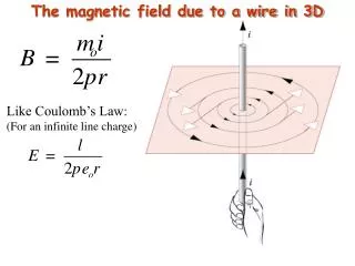
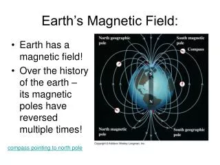
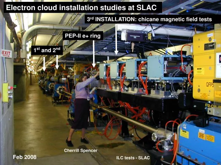
Electron cloud installation studies at SLAC. 3 rd INSTALLATION: chicane magnetic field tests. PEP-II e+ ring. 1 st and 2 nd. Cherrill Spencer. Feb 2008. ILC tests - SLAC. “Ecloud1” SEY test station in PEP-II SLAC. PEP-II LER. 2 samples facing beam pipe are irradiated by SR. e+ .

E N D
Electron cloud installation studies at SLAC 3rd INSTALLATION: chicane magnetic field tests PEP-II e+ ring 1st and 2nd Cherrill Spencer Feb 2008 ILC tests - SLAC
“Ecloud1” SEY test station in PEP-II SLAC PEP-II LER 2 samples facing beam pipe are irradiated by SR e+ Transfer system at 0o Isolation valves Transfer system at 45o ILC tests, M. Pivi et al. – SLAC ILC DR Workshop - KEK
Results of TiN conditioning in PEP-II e+ beam line Before installation in beam line After beam conditioning e- dose > 40mC/mm**2 ILC tests, M. Pivi et al. – SLAC SEY of Tin-samples measured before and after 2-months conditioning in the beam line. 2 samples inserted respectively in the synchrotron radiation fan plane (0o position) and out of this plane (45o). Similar low SEY recently measured in situ in KEKB beam line S. Kato, Y. Suetsugu et al. ILC DR Workshop - KEK
Surface analysis: Carbon content decrease TiN samples: X-ray Photon Spectroscopy. XPS Before installation XPS After exposure in PEP-II LER for 2 months (e dose 40mC/mm^2) LER#1 ILC tests, M. Pivi et al. – SLAC Carbon content is strongly reduced after exposition to PEP-II LER synchrotron radiation + electron + ion conditioning. This is a different result if compared to electron (only) conditioning in laboratory set-up where carbon crystals growth has been observed by many laboratories.
Results of NEG conditioning in PEP-II e+ beam line NEG as received After NEG heating After beam conditioning March 2008 ILC tests – SLAC
Clearing electrodes in KEKB magnetic free region Y. Suetsugu, KEK
SPS Groove Chamber Tests Collaborators Gianluigi Arduini, Elena Chapochnikova, Paolo Chiggiato, Miguel Jimenez, Mauro Taborelli (CERN) Mauro Pivi, Lanfa Wang, Frank Cooper, Munro Morrison (SLAC) Marco Venturini, Miguel Furman (LBNL) SPS meeting. Mauro Pivi SLAC
Secondary electron yield (SEY) estimate: SPS Groove In this simulation the groove height is taken to be the effective total height from top to valley Height=2mm Height=1mm Lanfa Wang, SLAC
Simulation of electron cloud build up Marco Venturini, LBNL electron cloud build-up as a function of time for 1mm deep grooves with angle alpha =80 deg, for various choices of the groove tip radius. Groove on bottom and top sides. In these simulations hg=1mm is the height of the groove triangle.
Simulation of electron cloud build up Marco Venturini, LBNL • Max. e-cloud linear density vs. groove tip radius (SEY=1.3) • For flat surfaces the max. linear density is ~ 1.5 nC/m). • In the SPS tests, grooves on top and bottom side. • In these simulations hg=1mm is the height of the groove triangle.
Roundness of tips and valley is important • Manufacture Tolerances on roundness are rather tight for 1mm grooves • Few more work on simulations: • In the SPS, would it be more realistic to assume initial SEY=1.5 (?!), since no photon scrubbing. • Define tolerance roundness to obtain SEY<1 • For small 1mm groove important to consider the effective groove height (after roundness)
TRIANGULAR GROOVE CHAMBER MFG January , 2008 munro
Requirements Triangular Grooves Groove Width 0.35 mm Groove Depth 1 mm Overall Depth 2 mm Groove Length 0.5 M Taper Angle 20 degrees Radius at Top & Bottom 0
Basic Problems • Very small grooves are difficult to fab • Sharp radii at base & top of grooves unattainable by normal mfg methods • Mfg options are to either have grooves as part of vac chamber, or fab grooves as separate item & then attach to vac chamber.
Mfg Options • Extrusion: Very small radii at top & bottom of grooves are difficult to mfg • Machining: Mill multiple slots in solid material • Metal Folding: Form multiple folds • EDM: Small radii are beyond normal tolerances • Brazed-up Assembly: Use individual razor type foil blades • Isostatic Pressing or Metal Injection Molding: Uses powdered metal & binders which would probably would not be suitable for vacuum usage. Also have difficulty in forming small radii
Groove Options Manufactured Series of aluminum extrusions fabricated • Grooves all around chamber (2 different groove profiles) • Grooves at top & bottom of chamber • Separate linear extrusion for insertion into existing stainless vacuum chamber
Cost Considerations • Assuming long sections required, the extrusion approach is by far the least expensive. • Limited to aluminum material • Copper may be possible, but could not find vender
Aluminum triangular grooves by ALMAG. Original design for the SPS: 2mm depth, limited by the groove sharpness. SLAC 2008
Aluminum triangular groove: depth 1.9mm, angle 20deg, radius top 0.095mm, radius valley 0.140mm
With final geometry The real geometry: radius of tip=0.095mm radius of valley =0.14mm Lanfa Wang, SLAC
Manufacturing Options depth 1mm: Metal Folding Metal Folding: Form multiple folds. [EMEGA Company, USA]
Manufacturing Options depth 1mm: Razor Blades Brazed-up Assembly: Use individual razor type foil blades