Download
1 / 58
590 likes | 851 Views
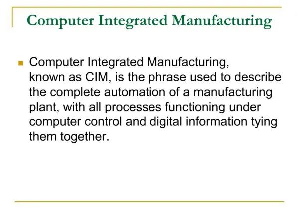
IE 447 COMPUTER INTEGRATED MANUFACTURING. CHAPTER 9 Material Handling System. Material Handling System. Material Handling is the movement, storage, control and protection of materials, goods and products throughout the process of manufacturing, distribution, consumption and disposal.

E N D
IE 447 COMPUTER INTEGRATED MANUFACTURING CHAPTER 9 Material Handling System IE 447 - CIM Lecture Notes - Chapter 9 MHS
Material Handling System IE 447 - CIM Lecture Notes - Chapter 9 MHS Material Handling is the movement, storage, control and protection of materials, goods and products throughout the process of manufacturing, distribution, consumption and disposal.
Material Handling System IE 447 - CIM Lecture Notes - Chapter 9 MHS The Material Handling System (MHS) is a fundamental part of a Flexible Manufacturing system since it interconnects the different processes supplying and taking out raw material, work-pieces, sub-products, parts and final products.
Material Handling System IE 447 - CIM Lecture Notes - Chapter 9 MHS Components: Robots Conveyors Automated Guided Vehicles(AGVs) Automated Storage/Retrieve System
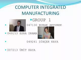
Robots in Manufacturing • Industrial robot is a • Programmable • Multi-functional • Designed to move materials, parts, tools or special devices • Through programmed motions • To perform many different tasks IE 447 - CIM Lecture Notes - Chapter 9 MHS
Robots in Manufacturing • First industrial robot was developed in the 1950s • Further advancements enable to utilize robots in • Variety of types • Style • Size • Their functionalities may include but not restricted to • Welding Drilling • Painting Military applications • Assembly Explosive material removal • Pick-and-place • Material handling IE 447 - CIM Lecture Notes - Chapter 9 MHS
Robots in Manufacturing • A typical robot consists of many different part connected to each other • Most robots resembles a human arm • Its motions are controlled by a computer program • Depends on the type of robot, movement capabilities of them are measured by the term degrees of freedom IE 447 - CIM Lecture Notes - Chapter 9 MHS
Robots in ManufacturingRobots with different degrees of freedoms 2-3 dof Robots used in surgery IE 447 - CIM Lecture Notes - Chapter 9 MHS
Robots in Manufacturing • How do robots work: there are 3 power sources IE 447 - CIM Lecture Notes - Chapter 9 MHS
Robots in Manufacturing • How do we know the location of robot arms? • Sensors are used to monitor the motion of robots • Motion of robots is sustained by the power based on the given input (computer algorithm) • Once the order is given, it is important to know the location of robot’s arm/parts • Its movements should be controlled during the entire motion • Robot should also be capable of sensing their environments • Sensors provides feedback to the controller and give flexibility to robots IE 447 - CIM Lecture Notes - Chapter 9 MHS
Robots in Manufacturing IE 447 - CIM Lecture Notes - Chapter 9 MHS
Robots in Manufacturing • Robot movements: • Robots are feasible when they are fast but also the stability is high • The trade-off between speed and stability is sustained by a powerful control system • Robotics and Control are two joint disciplines IE 447 - CIM Lecture Notes - Chapter 9 MHS
Robots in Manufacturing Robotic movements and joints • Robots required to perform • Rotational movements • Radial movements • Vertical movements • Type of joints • Rotational joints • Twisting joints • Revolving joints • Linear joints IE 447 - CIM Lecture Notes - Chapter 9 MHS
Robots in Manufacturing • Analysis of robot motions: Forward and Backward Kinematics concepts • Forward Kinematics: Transformation of coordinate of the end-effectors point from the joint space to the world space • Position of end-effectors is computed based on the joints locations • Backward Kinematics: Transformation of coordinates from world space to joint space • In this concept the position of end-effectors is known in world coordinate system • Required motion is computed based on this information IE 447 - CIM Lecture Notes - Chapter 9 MHS
Robot Configurations L2 (x2, y2) (x1, y1) L3 (x, y) (x, y) L1 (x, y) LL Robot: Base is static, arms are linear joints RRR Robot: Base is static, arms are rotational joints TL Robot: Base is rotational and the arm is linear joint IE 447 - CIM Lecture Notes - Chapter 9 MHS
Robots in Manufacturing • Essentials of robot programming • Requires • The path robot should follow • The points it should reach • Details about how to interpret the sensor data • How and when the end-effectors should be activated • How to move parts between given locations IE 447 - CIM Lecture Notes - Chapter 9 MHS
Robots in Manufacturing • Essentials of robot programming • Programming techniques • Teach-by showing: • Robot can repeat the motion already been done by the programmer • Textual language programming • A computer programming is written using logical statements • Some of the languages are: • Wave, VAL, AML, RAIL, MCL, TL-10, IRL, PLAW, SINGLA and ACL IE 447 - CIM Lecture Notes - Chapter 9 MHS
Robots of IE CIM LAB IE 447 - CIM Lecture Notes - Chapter 9 MHS
Robots of IE CIM LAB A four-axis, table-top mounted SCARA robot, the SCORA-ER 14 is designed for work in industrial training facilities. This rugged and reliable robot performs light-payload assembly, handling and packaging applications with impressive speed and accuracy. • Handling and packaging operations with palletizing and storage devices • Assembly operations with automatic screw driving and gluing devices • Quality control operations with machine vision and high-precision measurement devices SCORA ER14 IE 447 - CIM Lecture Notes - Chapter 9 MHS
Robots of IE CIM LAB The SCORBOT-ER 9 is a five-axis vertically articulated robot designed for work in industrial training facilities. With a multi-tasking controller that provides real-time control and synchronization of up to 12 axes, 16 inputs and 16 outputs, the SCORBOT-ER 9 supports both stand-alone applications as well as sophisticated automated work cells. SCORBOT ER9 IE 447 - CIM Lecture Notes - Chapter 9 MHS
Steps in Robot ProgrammingProgramming of an Industrial Task 1. Teach Pendant Operation • move the robot arm in • Joints • Cartesian • Tool coordinates • Control robot grippers and the speed of motion • Record positions to the robot controller’s memory • Move robot arm to recorded positions IE 447 - CIM Lecture Notes - Chapter 9 MHS
Steps in Robot ProgrammingProgramming of an Industrial Task 2. Writing robot programs • Use ACL (Automatic Control Language) to edit robot programs. • Commonly used robot program statements. MOVE: MOVED: OPEN: CLOSE: SPEED: IE 447 - CIM Lecture Notes - Chapter 9 MHS
Steps in Robot ProgrammingProgramming of an Industrial Task 3. Executing Robot Programs • Use ATS DIRECT Mode; • Statements to execute; RUN prgname : To execute the program prgname ABORT: To abort the current running robot program. IE 447 - CIM Lecture Notes - Chapter 9 MHS
Conveyors In CIM IE 447 - CIM Lecture Notes - Chapter 9 MHS Conveyors type: Belt Conveyors Roller Conveyors Crane Conveyors Screw Conveyors …
Conveyors In CIM IE 447 - CIM Lecture Notes - Chapter 9 MHS The package conveyor business has been in existence for almost one hundred years.Material handling engineering, in an over-simplified, basically, consists of determining "how a product should be moved from one place to another, within the shortest allowable period of time, for the least cost and with the least amount of manual effort".
Conveyors In CIM IE 447 - CIM Lecture Notes - Chapter 9 MHS Classification of conveyors: Active; Energy is supplied to the component for the movement of the materials, upward movements. Passive; No energy is supplied to the component and gravity force is utilized for the movement of the materials, mostly downward movements.
Conveyors In CIM IE 447 - CIM Lecture Notes - Chapter 9 MHS Classification of conveyors Continuous movement; Applicable for the movement of continuous materialsuch as liquids, sand, soil and cereals. District movement; Applicable for the movement of district materialsuch as boxes, parts, cans and…
Material Handling Systems Automatic Guided Vehicle Systems AGVS IE 447 - CIM Lecture Notes - Chapter 9 MHS
Understanding AGVS History of AGVS IE 447 - CIM Lecture Notes - Chapter 9 MHS
History of AGVS1953 First AGV • The first AGV system was built and introduced in 1953( A modified towing tractor that was used to pull a trailer and follow an overhead wire in a grocery warehouse) IE 447 - CIM Lecture Notes - Chapter 9 MHS
History of AGVS1973 Volvo Assembly Plant • In 1973, Volvo in Kalmar, Sweden set out to develop non-synchronous assembly equipment as an alternative to the conventional conveyor assembly line. The result was 280computer-controlled assembly AGVs. IE 447 - CIM Lecture Notes - Chapter 9 MHS
History of AGVS1970s First Unit Load • Introduction of a unit load vehicle They have the ability to serve several functions; a work platform, a transportation device, and a link in the control and information system They transport material in warehouses, factories, mills, hospitals, and other industrial and commercial settings. IE 447 - CIM Lecture Notes - Chapter 9 MHS
History of AGVSSmart Floors and Dumb Vehicles • In the 1970’s the principal guidance technology was to induce an electronic frequency through a wire that was buried in the floor. ‘floor controller’ • These first generation navigation schemes were expensive to install. • All floor cuts needed to follow the exact path of the AGV. IE 447 - CIM Lecture Notes - Chapter 9 MHS
History of AGVSDead Reckoning Capability • As the vehicles became more intelligent, the path became less sophisticated • Dead reckoning is a term that describes the ability of a vehicle to traverse steel expansion joints on the factory floor or to cross a steel grate The biggest advantage was that dead reckoning eliminated the need to make the cut radius turns at intersections. (Installation was greatly simplified). IE 447 - CIM Lecture Notes - Chapter 9 MHS
History of AGVS1980s Non-Wire Guidance • The introduction of laser and inertia guidance. • Allow for increased system flexibility and accuracy • No need for floor alterations or production interruption IE 447 - CIM Lecture Notes - Chapter 9 MHS
AGV NAVIGATION • The principles which make it possible for an AGV to navigate its way between any two locations are really quite simple. All navigation methods use a path. The vehicle is instructed to Follow a Fixed Path or Take an Open Path. IE 447 - CIM Lecture Notes - Chapter 9 MHS
Fixed Path NavigationFollowing a Path • The paths are well marked on the floor • The paths are continuous • The paths are fixed, but can be changed IE 447 - CIM Lecture Notes - Chapter 9 MHS
Fixed Path Navigation: Creating a Path The principle techniques for creating paths are to: • Apply a narrow magnetic tape on the surface of the floor • Apply a narrow photo sensitive chemical strip on the surface of the floor • Apply a narrow photo reflective tape on the surface of the floor • Bury a wire just below the surface of the floor IE 447 - CIM Lecture Notes - Chapter 9 MHS
Fixed Path Navigation: Buried Wire Path • Bury a current-carrying wire just below the surface of the floor IE 447 - CIM Lecture Notes - Chapter 9 MHS
Fixed Path Navigation: Steering Correction Coils • The vehicle steers itself to FOLLOW the magnetic field surrounding the buried wire. IE 447 - CIM Lecture Notes - Chapter 9 MHS
Fixed Path Navigation: Path Selection • In this illustration, a vehicle at “A” has two choices on how to get to “B”. A computer either on board the vehicle or at some central location selects a path based on established criteria. • Criteria: • The shortest distance • The path with the least traffic at the present time • All of the “PATH FOLLOWING” methods permit routing options that include guide path switching and merging. IE 447 - CIM Lecture Notes - Chapter 9 MHS
Open Path Navigation: Taking a Path • Unlike “path following navigation,” where the guide paths are fixed, and more or less permanent, vehicles operating in the “Take a Path” category are actually offered more variation if not an infinite number of ways to navigate the open space between two points. IE 447 - CIM Lecture Notes - Chapter 9 MHS
Open Path Navigation: Navigation Methods • The three most common open space navigation methods are: • Laser Guidance • Inertial Guidance • Cartesian Guidance The choice of navigation method for aparticular application is often a simple matter of preference. IE 447 - CIM Lecture Notes - Chapter 9 MHS
Navigation Methods - Laser Guidance • Reference points are strategically located targets • A beacon on top of the vehicle emits a rotating laser beam which is reflected back to the vehicle when it strikes (sees) a target. IE 447 - CIM Lecture Notes - Chapter 9 MHS
Navigation Methods - Inertial Guidance • An on board gyroscope establishes and maintains a vehicle’s heading. • Distance traveled is calculated by an on board encoder which counts wheel rotations. IE 447 - CIM Lecture Notes - Chapter 9 MHS
Navigation Methods – Cartesian Guidance • Location precision is accomplished by way of a fixed grid pattern that covers the entire floor area. • The possible travel paths in a given, unrestricted operating area for a grid based system are infinite and most like that provided by laser guidance IE 447 - CIM Lecture Notes - Chapter 9 MHS
AGVS Dispatching • Dispatching AGVS is much the same as dispatching taxi cabs. • The dispatch function makes sure that all customers get timely services from the vehicle best able to service a request. • Remoteand local dispatch are most commonly described as offboardand onboard dispatchers respectively. IE 447 - CIM Lecture Notes - Chapter 9 MHS
AGVS Communications • Communications include message commandssuch as: • where to go, • when to start, • when to slow down, • when to stop. • Four types of basic communication media: • Radio Communication • Infrared Communication • Guide Wire Data Communication • Inductive Loops Communication IE 447 - CIM Lecture Notes - Chapter 9 MHS
AGVS Communications Radio Communication • Maximum flexibility in system control • Vehicles can be programmed “on the fly” • system speed of response to changing load movement demands is improved IE 447 - CIM Lecture Notes - Chapter 9 MHS
AGVS Communications Infrared Communication • Optical infrared communication is highly reliable but has the disadvantage of not being continuous; it is point to point. • Vehicles may be stopped during this data exchange which usually occurs at load stations where the fixed and mobile units are aligned and in close proximity. • Or, the vehicle communicates at fixed points along its guide path as the vehicle travels through a given zone. • Infrared communication is best suited for small systems with few vehicles and load stations. IE 447 - CIM Lecture Notes - Chapter 9 MHS