Download
1 / 23
230 likes | 324 Views
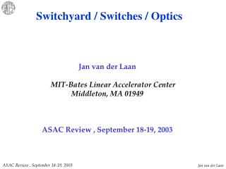
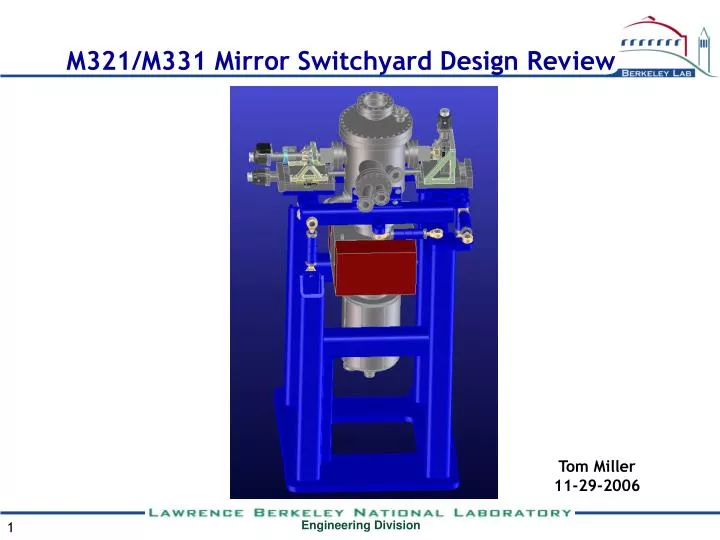
M321/M331 Mirror Switchyard Design Review. Tom Miller 11-29-2006. Basic layout of M321/M331 mirror switchyard. y. y. z. z. x. x. M321. M321. M331. M331. Figure 4: Coordinate system of mirror switchyard. Figure 4: Coordinate system of mirror switchyard.

E N D
M321/M331 Mirror Switchyard Design Review Tom Miller 11-29-2006
y y z z x x M321 M321 M331 M331 Figure 4: Coordinate system of mirror switchyard Figure 4: Coordinate system of mirror switchyard Alignment, resolution and stability requirements Alignment / stability tolerance and mechanical steps for M321 and M331 (Yaw) (Pitch) (Roll)
Basic Optic Design • One optic versus two • Single optic advantages: • No mechanisms for alignment between M321 • & M331 • Lighter and more rigid optic and mounting • for better stability • Smaller required translation due to compact • design • Faster setup and commissioning due to fixed • angle between M321 & M331 • Single optic disadvantages: • Up-front cost of the optic. This can be offset by reduced mechanism and setup costs if • optics are not routinely damaged • Manufacturing tolerances on the relationship between the two optical surfaces must be • good for quick replacement of the optic. Single optic for M321 and M331 with diagnostic pass – through. Mounting details are omitted
Maximum Required Motions Translations(x): (Single optic) RIXS Rotated: 12.01mm outbound ARPES Rotated: 17.97mm inbound Total: 29.98mm (nominal) Pitch (Thetay ): (Single or dual optics, RIXS & ARPES) High Res grating: +/-259 microradians High Flux grating: +/-168 microradians Roll (Thetaz ): (Single or dual optics, RIXS & ARPES) +/- 5 milliradians RIXS rotated ARPES rotated
Mechanism Fundamentals Initial concept: Mount the optic(s) rigidly in the chamber and translate the chamber with a single slide and pitch and roll with struts to steer the beam. Advantage: • Familiar approach • Easy installation survey. The optic(s) can be accurately fiducialized in a lab and those numbers used for installation alignment. Disadvantages: • Input and outputbellows are required. Large and variable off-axis forces act on the translation slide and rotation mechanisms • If pumping is added to the chamber, the pump must move with the chamber or be bellows isolated. This will result in a large mass offset from the slide or more non-constant bellows forces. Both solutions result in poorly placed variable forces. • Pitch and roll motions intrinsically couple to all other motions. • Parasitic motions from variable off-axis forces may make high resolution encoder readings meaningless
Mechanism Fundamentals New concept: Mount the chamber rigidly and move the optic(s) Advantages: • Bellows forces are small and self-cancelling • Pitch corrections are nominally independent of roll • Translations are nominally independent of pitch and roll • Any force required for translation is small and almost directly in line with the linear bearings in the stages. • All sources of backlash in the mechanism are spring loaded in the axis of freeplay. • Pitch and roll are flexure-based motions and therefore very repeatable • Large pumps can be mounted beneath the tank with no effects on motion. • Small off-axis forces will make encoder readings more meaningful • The moving masses are small and the mechanisms optimized for stiffness. The vibrational modes of the mechanism are thus above 200Hz. • All mechanism parts are stainless steel or cast iron. This should yield good thermal stability.
Mechanism Fundamentals New concept: Mount the chamber rigidly and move the optic(s) Disadvantages: • Unfamiliar design • Roll couples to pitch and translation. 1 milliradian of roll induces 200 microradians of pitch for ARPES, 100 microradians of pitch for RIXS and 0.13 microns of translation. Intrinsic roll errors should be very small, and thus the roll corrections should also be small, so pitch coupling should not be a problem. Translation coupling will be insignificant. • Pitch couples to translation. 250 microradians of pitch results in 9 microns of translation at the nominal reflection point. The large pitch changes required for grating selection also have an associated ~1.5mm translation, so this number is acceptable. • Installation surveys of the optic will be relatively imprecise. The orientation of the optic to outside fiducials must be determined after the optic is mounted in the tank. The in-vacuum fiducials are close together and difficult to survey in the tank.
Cost estimate Fab and purchases: $78,000 Assembly (200hrs) : $20,000 Total: $100k