Download
1 / 35
370 likes | 544 Views
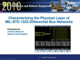
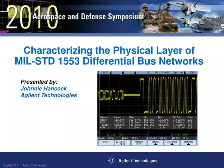
Characterizing the Physical Layer of MIL-STD 1553 Differential Bus Networks. Presented by: Johnnie Hancock Agilent Technologies. Objectives

E N D
Characterizing the Physical Layer of MIL-STD 1553 Differential Bus Networks Presented by: Johnnie Hancock Agilent Technologies
Objectives Learn how to quickly verify the electrical/physical layer input and output characteristics of MIL-STD 1553 differential serial buses using a Digital Storage Oscilloscope (DSO) with MIL-STD 1553 bus decoding and triggering capability. Learn how eye-diagram mask testing can provide a composite measure of the signal integrity of your MIL-STD 1553 differential bus.
Agenda • MIL-STD 1553 Protocol & Timing Overview • MIL-STD 1553 Electrical/Physical Layer Requirements • Triggering and Decoding MIL-STD 1553 Serial Buses • Isolating Physical Layer Measurements on Remote Terminal (RT) and Bus Controller (BC) generated Signals • MIL-STD 1553 Eye-diagram Mask Testing • Clock Recovery Technique
MIL-STD 1553 Protocol & Timing Overview • Word Length = 20 bits (3-bit Sync field, 16-bit content field, 1-bit parity field) • Word Types: • Command (Packets transmitted by BCs) • Status (Packets transmitted by RTs) • Data (Packets transmitted by BCs and RTs) • Baud Rate = 1 Mb/s • Encoding = Manchester II Bi-phase (except 3-bit Sync field)
Manchester II Bi-phase Encoding • NRZ Encoding • High during middle of bit time = 1 • Low during middle of bit time = 0 • Manchester II Bi-phase Encoding • High to low transition in middle of bit time = 1 • Low to high transition in middle of bit time = 0
Message Formats (Master/Slave Relationship) Example #1: BC to RT Transfers (BC sends data to RT) A B B B C • A Packet - Command Word from BC to RTA = 0F w/ receive bit set: “Get ready accept data.” • B Packets - 5 Data Words transmitted from BC to RT • C Packet - Status Word from RTA = 0F: “Got it!” B B B B B A C Note: Signals probed at BC input/output test plane
Message Formats (Master/Slave Relationship) • Example #2: RT to BC Transfers (BC requests data from RT) A B C C C • A Packet - Command Word from BC to RTA = 02 w/ transmit bit set: “Send me data.” • B Packet - Status Word from RTA = 02: “Here it comes!” • C Packets - 4 Data Words transmitted from RT to BC B C C C C A Note: Signals probed at RT input/output test plane
Message Formats (Master/Slave Relationship) • Example #3: RT to RT Transfers (BC requests RT “2” to send data to RT “1”) E A B C D D D • A Packet - Command Word from BC to RTA “1” w/ receive bit set: “Get ready accept data.” • B Packet – Command Word from BC to RTA “2” w/ transmit bit set: “Send data to RT “2”.” • C Packet – Status Word from RTA “2”: “Here it comes!” • D Packets - N Data Words transmitted from RT “2” to RT “1” • E Packet – Status Word from RTA “1”: “Got it!” C D D D D A B E Scope waveforms not available Note: Signals probed at RT2 input/output test plane
Primary Electrical/Physical Layer Specifications Other Important Timing Parameters Intermessage Gap: ≥ 4 µs (parity bit crossing to next sync edge) Response Time: 4 to 12 µs (parity bit crossing to next sync edge)
Measurement Test Planes • All terminals are transceivers. • Both output/transmitted and input/received signals are present at all differential terminal I/O pins. • Making oscilloscope parametric and timing measurements on specific transmitted or received words can be enhanced with “intelligent” oscilloscope triggering. Data Device Corporation Graphic
The Problem: Most of today’s scopes trigger on simple edge crossing conditions • Simple “edge” triggering can’t differentiate between transmitted and received words. • External/synchronization signals are rarely available. • Resultant measurements and display are composites of ALL words.
Required MIL-STD 1553 Triggering 1 2 1 3 • Input Measurements • Received signals at BC transmitted from RT1 • Probe at BC • Trigger on Status Words from RTA = 1 • Output Measurements • Transmitted signals at BC • Probe at BC • Trigger on Command Words • Transmitted signals at RT1 • Probe at RT1 • Trigger on Status Words from RTA = 1 • Received signals at RT1 transmitted from BC • Probe at RT1 • Trigger on Command Words • Received signals at RT2 transmitted from RT3 • Probe at RT2 • Trigger on Status Words with RTA = 3 • Transmitted signals at RT2 • Probe at RT2 • Trigger on Status Words with RTA = 2 • Transmitted signals at RT3 • Probe at RT3 • Trigger on Status Words with RTA = 3 Note 1: Bus Monitor (protocol analyzer)
MIL-STD 1553 Option Triggering on MIL-STD 1553 Signals Triggering options: • Data Word Start • Data Word Stop • Command/Status Word Start • Command/Status Word Stop • Remote Terminal Address • RTA + 11 Bits • Parity Error • Sync Error • Manchester Error Note: The “RTA + 11 bits” trigger mode can be used to trigger on and differentiate between specific Command and Status Words.
MIL-STD 1553 Option Command versus Status Word Triggering Using the “RTA + 11 bits” Trigger Mode Command Word Trigger Status Word Trigger Trigger Status Word Status Word Trigger Command Word Command Word Trigger: RTA + 11 bits = 02HEX + 1 11110 XXXXX Trigger: RTA + 11 bits = 02HEX + X 0X000 XXXXX Sub-address = 30 (decimal) Status bits
Measuring received signals at RT2 transmitted by the BC Rise Time & V p-p @ RT input 2 1 3 Command Word received from BC T/R Sub-Address MIL-STD 1553 Trigger Setup (Command Word Trigger: RTA = 2, Transmit, Sub = 1110)
Measuring received signals at RT2 transmitted by the BC Response Time 2 1 3 Response Time T/R Sub-Address MIL-STD 1553 Trigger Setup (Command Word Trigger: RTA = 2, Transmit, Sub = 1110)
Measuring received signals at RT2 transmitted by the BC Intermessage Gap Time 2 1 3 Intermessage Gap T/R Sub-Address MIL-STD 1553 Trigger Setup (Command Word Trigger: RTA = 2, Transmit, Sub = 1110)
MIL-STD 1553 Eye-diagram Mask Testing Eye-diagram measurements provide a composite measure of overall system signal integrity by overlaying all bits of each word. • Eye-diagrams display worst-case jitter, vertical noise, & signal anomalies. • Conventional eye-diagrams measurements require a reference clock signal for triggering. • MIL-STD 1553 signals don’t supply an explicit reference clock signal. • Generating MIL-STD eye-diagram measurements requires either a software- or hardware-recovered clock. Vertically closing eye due to noise and/or insufficient signal level Horizontally closing eye due to jitter and/or signal timing errors
MIL-STD 1553 Hardware Clock Recovery Algorithm Scope triggers on specific word in order to capture and display input or output signals at a particular test plane. Scope’s timebase is scaled to repetitively capture just the 1st Manchester-encoded bit (bit #4) for 50 milliseconds with infinite-persistence turned on. Scope’s timebase is scaled to repetitively capture just the 2nd Manchester-encoded bit (bit #5) for 50 milliseconds with infinite-persistence turned on. Scope steps through and repetitively captures all 17 Manchester-encoded bits (bits 4 through 20) for 50 milliseconds each with infinite persistence turned on, and then repeats. Note: This is an automated test sequence that runs within the scope when a MIL-STD 1553 mask test file is recalled.
“Building” the MIL-STD 1553 Eye Bit #4 Bit #5 Bit #6 Bit #7 Bit #8 Bit #9 Sync Field = Bits 1 - 3 … … Bit #7 Bit #5 Bit #6 Bit #8 Bit #9 Bit #4 Bits 4 - 20
The MIL-STD 1553 “Double Eye” • With Manchester encoding, the MIL-Std 1553 eye-diagram measurement consists of 2 eyes/bit. • Signal transitions should always occur near mid-point of each bit time. • Signal transitions may or may not occur near bit time boundaries. • The diamond-shaped pass/fail mask is based on the “voltage swing” (0.86 V p-p for xformer coupled @ input test plane) and “zero-crossing-distortion” (+/- 150 ns @ input test plane) specifications.
Summary • The electrical/physical layer of MIL-STD 1553 networks should be characterized to insure good signal integrity for reliable communication. • Using an oscilloscope with built-in MIL-STD 1553 triggering and decoding will enhance your ability to quickly window-in on specific transmitted and received words for physical layer characterization. • MIL-STD 1553 eye-diagram mask testing provides a composite measure of your systems physical layer characteristics.
Agilent’s InfiniiVision Series Oscilloscopes Engineered for Best Signal Visibility DSO5000A MSO/DSO6000L MSO/DSO6000A MSO/DSO7000B Option 553: MIL-STD 1553 Trigger & Decode Option LMT: Mask Testing N2791A: 25-MHz Differential Active Probe
Application-specific Measurement Options forInfiniiVision Series Oscilloscopes
Characterizing the Physical Layer of MIL-STD 1553 Differential Bus Networks Q & A Thank you for your time today!
MIL-STD 1553 Option Agilent’s InfiniiVision Series Oscilloscopes for MIL-STD 1553 Testing (Option 5531) • Compatible models: All 5000, 6000, and 7000 series 4-channel DSOs and 4+16 channel MSOs • Industry’s only hardware-based decode enhances probability of capturing MIL-STD 1553 communication errors • Flexible MIL-STD 1553 triggering modes • Automatic Search & Navigation (7000B only) • Optional battery operation (6000A series only) • MIL-STD 1553 eye-diagram mask testing (requires Option LMT2) • Entry-level Price: • DSO5014A - $5300 • Option 5531 - $1300 • Option LMT2 - $ 700 • N2791A Diff Probe - $ 600 • Total System Price - $7900 Notes: For after-purchase upgrade on an existing oscilloscope order N5469A. For after-purchase upgrade on an existing oscilloscope order N5455A.
MIL-STD 1553 Option Decoding the MIL-STD 1553 Bus • Decode Display: • “Lister” table • Time-aligned trace • Numeric/Symbol Format: • HEX • Binary • Basic Word-type Symbol • Word Type: • Cmd/Status (green) • Data (white) • Bits: • Remote Terminal Address (green) • Command/Status Bits 9-19 (green) • 16 Bits of Data Word (white) • Errors • Parity (red) • Sync (red) • Manchester (red) Decode “Lister” Time-aligned Decode Trace
MIL-STD 1553 Option Time-Aligned Decode Trace Binary Decode Data Word Sync Command/Status Word Sync HEX Decode RTA 11 Bits 16 Bits Word Type Word Type
MIL-STD 1553 Option Triggering on MIL-STD 1553 Signals Triggering options: • Data Word Start • Data Word Stop • Command/Status Word Start • Command/Status Word Stop • Remote Terminal Address • RTA + 11 Bits • Parity Error • Sync Error • Manchester Error Note: The “RTA + 11 bits” trigger mode can be used to trigger on and differentiate between specific Command and Status Words.
MIL-STD 1553 Option Command versus Status Word Triggering Using the “RTA + 11 bits” Trigger Mode Command Word Trigger Status Word Trigger Trigger Status Word Status Word Trigger Command Word Command Word Trigger: RTA + 11 bits = 02HEX + 1 11110 XXXXX Trigger: RTA + 11 bits = 02HEX + 0 00000 00000 Sub-address = 30 (decimal) Status bits
MIL-STD 1553 Option Error Analysis and Triggering Sync Error Parity Error Manchester Encoding Error Manchester Encoding Error = Missing transition within bit time
MIL-STD 1553 Option Automatic Search & Navigation
MIL-STD 1553 Option MIL-STD 1553 Mask Test Files • Free downloadable mask files: • System xfmr-coupled Input.msk • System direct-coupled Input.msk • BC to RT xfmr-coupled Input.msk • BC to RT direct-coupled Input.msk • RT to BC xfmr-coupled Input.msk • RT to BC direct-coupled Input.msk • RT to RT xfmr-coupled Input.msk • RT to RT direct-couple Input.msk MIL-STD 1553 eye-diagram mask test files can downloaded at: www.agilent.com/find/1553
MIL-STD 1553 Option Probing a MIL-STD 1553 Differential Bus Probe Output • The MIL-STD 1553 differential bus must be probed with a differential active probe. • Output of differential probe must be fed into two channels of the scope in order to establish dual threshold triggering (upper and lower thresholds). Agilent’s N2791A 25-MHz differential active probe is recommended (US$600).