Download
1 / 19
190 likes | 196 Views
ETD PID meeting. FTOF FARICH Measurement of the FTOF single channel time resolution validated by simulation BARREL Status on activities at Bari Status on French developments On behalf of PID group. FARICH ( E.A.Kravchenko). FARICH. Electronics ( preliminary design )

E N D
ETD PID meeting • FTOF • FARICH • Measurement of the FTOF single channel time resolution validated by simulation • BARREL • Status on activities at Bari • Status on French developments • On behalf of PID group Christophe Beigbeder ETD- PID meeting
FARICH (E.A.Kravchenko) Christophe Beigbeder ETD- PID meeting
FARICH • Electronics ( preliminary design ) • Fast FPGA could be used as TDC : smaller number of components – it is easier to fit FARICH • electronics into available space • zero dead time • Flexible logic • Commercially available • Low cost (~0.5 Euro/channel) See also DCH talk from • Constraints : • 8 channels, 1664/8 = 208 chips on board / sector • FPGA TDC (Cyclone III) – 23x23 mm frame, • 60 channels, 1664/60 – 28 chips on board • 10 Gb optical link(XFP) • 50 W / 46 mm thikness • FE ASIC – several candidates: • DIRC ASIC / NINO13 chip Main Remark : Study has to be done on the radiation level at this point Total dose. Particle flux . Christophe Beigbeder ETD- PID meeting
Measurement of the FTOF single channel time resolution validated by simulation ( Leonid) • Two quartz bars connected to one Photonis MCP-PMT (8x8 channels, stepped face, 10 micron holes). • Tube operate at -2.7kV (gain ~ 7.0x10⁵). • 16 channels connected to the USBWC electronics developed by LAL and CEA/IRFU electronics team. • Amplifiers (40dB). • Filters (600MHz bandwidth ). • Installed at SLAC CRT in Fall 2010. MCP-PMT pixel map J. Va'vra
Upgraded vs old setup We add a mylar sheets between MCP-PMT and quartz bars. Thanks to that the number of p.e. reduced by a factor of ~5. Rise time channel 2 Number of channels in one event with amplitude more than 80 mV + basic cuts. Old setup Laser Old setup New setup Laser New setup # of channels with signal Average number of channels with signal is 4. This is good compromise between running the tube in “clean” conditions and have a reasonable statistic.
The time resolution measurements of the FTOF prototype We use only reconstructed muons We apply sanity cuts on waveform (amplitude > 80mv, shape, number of channels with signal) Time difference between channels are used in order to estimate resolution. Top to bottom time difference Not neighbor channels connected to same quartz bar We compare data with simulation
Results swide = 409 ps snarrow = 100 ps Measurements G4 simulation ch5-ch13 ch11 - ch13 # of ev. 3610 G4 simulation + waveform simulation Measurements snarrow = snarrow/sqrt(2)= 70ps/channel
Conclusions New setup and software give results cleaner and easier to understand. Simulation is not final yet but already quite precise including geometry and waveform parametrization. Data/MC agreement is reasonable for all the time differences between channels studied so far. We measure 70ps /channel time resolution, to applying basic cuts of the waveform. Note with old setup we get 90ps/channel we were obliged to make a cut on rise time of the waveform. stot = sdet sTTS selectronics swaveform sdet swaveform ~60ps sTTS ~35ps selectronics ~10ps
Activites in Bari Two main topics : Electronics for the CRT and a test facility for PM studies. • Common Requirements • Easy coupling with our MaPMT (H8500) • Fast shaping time (for timing studies) • Good gain (to «clearly see» the single p.e) • Design based on commercial electronics components The goal is to have the electronics compatible with different DAQ systems At the moment it is tailored to work with CAEN VME modules • Differential Output for Charge measurements with a 64ch ADC • Differential ECL Output for timing measurements with a 64ch TDC Christophe Beigbeder ETD- PID meeting
16 Ch board CAEN VME TDC VN1488 (borrowed) •64 input (Differential ECL) •Full scale (100ns – 1600ns) •Resolution (25ps-400ps) CEAN VME ADC VN1465 (borrowed) •64 input •Full scale (200pC – 1600pC) •Resolution (50fC – 400fC) Christophe Beigbeder ETD- PID meeting
A test facility in Bari • To study the performances of the MaPMT • To perform some ancillary checks such us cable cross talk, light source calibration and so on • To study the performances of all the readout chain (Electronics + MaPMT) in the final configuration. • In this case a new DAQ system will be developed to match the common accepted standard . • Write analysis tools (ROOT/Python scripts) -> CTR data sudies and for the futur electronics chain Christophe Beigbeder ETD- PID meeting
French activities “Young researcher project “( N. Arnaud ) submitted on PID project. Summing up all the numbers the total cost for the whole FDIRC electronics prototypes chain is 130 k€. Answer July 2011 Christophe Beigbeder ETD- PID meeting
SCATS status Design almost finished : Verilog and simulation in Actel FPGA done . Some problems to target code in AMS library Some problems with IC tools : mixed digital and analog simulation Layout in progress . Final assembling to be done . From 20MHz to 300 MHz Christophe Beigbeder ETD- PID meeting
Memory design architecture and layout 32 Width x 8 Depth fifo W0 W1 W7 En Fifo1 B<0> B<1> 16 B<15> 32 W0 W1 W7 En Fifo2 B<0> B<1> 16 B<15> AMS CMOS 0.35µm technology 1000µm 120µm Christophe Beigbeder ETD- PID meeting
Post layout simulations with parasitic extraction: Typical mean parameters: out_fifo1<0> rise time : 2.26 ns – maximum dispersion from memory cell to memory cell: 300ps Worse power parameters out_fifo1<0> rise time : 1.66 ns >>>>Match the requirements of a 40 MHz FIFO Worse time parameters: out_fifo1<0> rise time : 3 ns Christophe Beigbeder ETD- PID meeting
Test boards Mezzanine : - CFD/ CFD like + Amp for charge measurement. - PIF chip in next version -> equips both PM test setup @ Orsay and CRT Mother board : ADC + Scats + FPGA - Associate time & charge - Data packing. - Bus interface : Vme, GVbus -> equips both PM test setup @ Orsay and CRT Christophe Beigbeder ETD- PID meeting
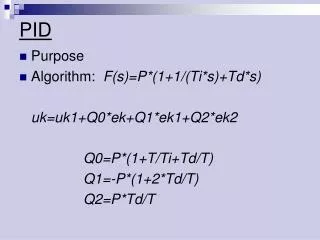
PIF : Architecture In00 Charge Amplifier Sample & Hold Mux Charge output (To ADC) Synchronization with TDC data State Machine Fast comparator Pseudo CFD ToTDC Fast comparator Classical CFD Proposed pseudo CFD Delay + Fraction <-> Gain + Integrators Christophe Beigbeder ETD- PID meeting
Implementation & Simulations in AMS CMOS 0.35µm Input amplitude: from 1 to 100 Zero cross Difference between amplified signal and delayed amplified signal Walk ~ 70 ps 50 ps (dynamic of 10) Christophe Beigbeder ETD- PID meeting
Conclusion • FTOF • A lot of activities was presented during the session concerning the 3 proposals for the TOF • The task force should give its conclusion @ Elba . • Barrel • A lot of work on PM tests, scanning setup and developments on the CRT are ongoing @ SLAC by SLAC people. • Bari brings detector expertise. The work is oriented toward PM qualification ,CRT tests, test bench for the final design. • French people are involved in the electronics to equip the detector • SCATS and PIF designs are on tracks. SCATS submission in July. -> A lot to do for the TDR : backplane, power supplies, cooling, integration … - >We all have to be careful to coordinate these activities and not do the same thing @ different places -> We all have to be careful to design a electronics which can fit the CRT requirements in terms of dimension and acquisition protocol Christophe Beigbeder ETD- PID meeting