Download
1 / 52
540 likes | 738 Views
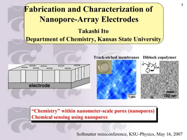
Synthesis, characterization and modeling of porous electrodes for fuel cells Hao Wen Prepared for defense practice talk 3/29/2012. Fuel cells - overview. Motor vehicles. Load. current. Portable device power supply. Fuel. Air. Electrolyte. Anode. Cathode.

E N D
Synthesis, characterization and modeling of porous electrodes for fuel cells • Hao Wen • Prepared for defense practice talk • 3/29/2012
Fuel cells - overview Motor vehicles Load current Portable device power supply Fuel Air Electrolyte Anode Cathode Fuel cells convert chemical energy into electricity Applications varies from high temperature high power output to room temperature portable power sources. http://www.fllibertarian.org/ Biofuel cells Barton, S.C., AlCHE annual meeting
Multiscale porous electrode support Fuel transport Support Too much porosity lowers conductivity Electrolyte e- e- e- Product Catalyst Reactants Reactants Reactants Mesopores Interfacial reaction Current collector
Synthesis of carbon porous electrodes Carbon nanotube Carbonaceous foam monolith Exfoliated graphite Template introduced macro-pore Surface modification, compositing, and coating with catalyst www.nanocyl.com J. Lu 2007, Chemistry of Materials O. Velev, 2000, Advanced Materials Flexer, 2010, Energy and Environmental Science
Modeling scheme OUTUT INPUT Geometry RDE PRDE Film Porous layer Measurable Impedance Polarization Cyclic voltammetry Hardly Measurable Concentration profile Active region Porous Electrode Model Kinetics Ping pong bi bi Differential linear kinetics Optimization Electrode thickness Porosity Feeding rate Transport Fuel / Oxygen In Channel,porous layer
Porous electrodes under study CNT Carbon fiber Carbon nanotube coated carbon fiber microelectrode Polystyrene derived macro-pore embedded CNT coated carbon fiber microelectrode ω Porous media SOFC composite cathode Porous rotating disk electrode diameter
Outline • Carbon nanotube modified electrodes as support for glucose oxidation bioanodes • Polystyrene bead pore formers • Analysis of transport within porous rotating disk electrode • Solid oxide fuel cell composite cathode model
Carbon Nanotube Modified Electrodes As Support For Glucose Oxidation Bioanodes
Carbon Paper / CNT Electrode CNT grown on carbon paper CNT growth time effect Substrate concentration gradient Current Collector S. C. Barton et al, Electrochem. & Solid State Lett., 10, B96 (2007). 100 µm
Carbon Fiber Microelectrode Glass capillary Heat pulled fine tip Cu wire Exposed fiber Carbon paste Epoxy Glass ends Transition from glass capillary tip to fiber
Fabrication Procedure Carbon nanotubes CNT Coating Biocatalyst coating N,N-Dimethylformamide Pipette CNT suspension Pipette Biocatalyst Coating Carbon Fiber sonication CNT Coated Fiber CNT Dispersion
Carbon Fiber / CNT Electrode fiber CNT 1μm 5 μm Focused Ion Beam Cut Cross Section + SEM Side View Fiber electrode
Coating thickness and capacitance • Capacitance • The initial increase is 7.9 µF/µg • Thickness • CNT coating layer density can be estimated: 1.0×10⁻⁶µg µm-3 • Capacitance measured in 20 mM PBS solution with 0.1 M NaCl. • The coating thickness was measured digitally by optical micrograph. • Surface area conversion factor: 1.5 μF/cm2
Biocatalyst test system Electrolyte Redox hydrogel Glucose oxidase Glucose Glucono lactone Redox polymer – the mediator e- e- e- e- Redox potential: PVI-[Os(bpy)2Cl]2+/3+ 0.23 V vs Ag/AgCl Electronically conductive Carbon support B. Gregg and A. Heller, J. Phys. Chem. 95, 5970 (1991).
CFME/CNT/Hydrogel Performance 1.76 x 10⁴ Ω Redox polymer test 50 mV/s Electrochemical cell Internal resistance Potentiostat Internal resistance Polarization curve 1 mV/s Performance summary • Performance • 6.4 fold increase of current density at 0.5 V to 16.63 mA cm-2. 50 mM glucose, 20 mMphophate buffer solution, 0.1 M NaCl as supporting electrolyte, 37.5 ⁰C, 150 rpm stirring bar, nitrogen saturated.
Polystyrene Bead Template Introduced Macro-pores In Carbon Nanotube Porous Matrix
Polystyrene introduced macro-pores Macroporosity was introduced to enhance transport Application to CFME Biocatalyst Heat Treatment Polystyrene beads Mixing Dried Carbon nanotubes PS removed N,N-Dimethylformamide fiber fiber fiber CNT matrix PS introduced pores + sonication Biocatalyst + + Chai, G.S., Shin, I.S. & Yu, J.-S. Advanced Materials16, 2057-2061(2004).
FIB-SEM cross-sectional view CNT only on CFME PS + CNT + CFME PS removed by heat treatment Hydrogel coated CFME
SEM side view CNT only on CFME PS + CNT + CFME PS removed by heat treatment Hydrogel coated CFME
Electrochemical test • Both active medaitor and glucose oxidation current doubled; • Larger loading of PS over close packing with total filled CNT led to decrease in performance
Analysis Of Transport Within Porous Rotating Disk Electrode (PRDE)
Porous rotating disk electrode (PRDE) RDE PRDE ω electrode http://www.pineinst.com/ Flow field within porous media Flat surface; Well-solved fluid flow field. permeability Assuming fast kinetics Kinematic viscosity The analytical flow field assume infinite PRDE radius Nam, B. & Bonnecaze, R.T. , Journal of The Electrochemical Society154, F191(2007).
Experimental system to be modeled Experimental data to be modeled carbonaceous foam electrode RDE 2190 µg cm-2 2190 µg cm-2 ω 100 mM glucose 0.5 V vs. Ag/AgCl 340 µg cm-2 Mediator (redox polymer) • 74% porosity • Hierarchical multi-scale porosity Electrochemical reactions The redox potential: 350 mV vs Ag/AgCl. PAA-PVI-[Os(4,4’-dichloro-2,2’-bipyridine)2Cl+/2+]
Model setup PRDE Electrolyte Zero flux Electrolye solved flow field Enzyme reaction rate Interface continuity
Fitting results by considering diffusion • Phenomena considered: Diffusion at all rotations; Boundary layer in electrolyte; Natural convection;
Concentration profile Convection dominant Diffusiondominant region Diffusion is dominant in low rotation, and high rotation, but closer to current collector surface
Geometric parameters Electrode thickness effect Permeability effect • Large thickness doesn’t lead to higher current at low rotations due to limited active region; • Higher permeability generate higher current at lower rotations
Solid Oxide Fuel Cell Composite Cathode Impedance Model With Low Electronic Conductivity
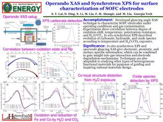
Experimental setup – Symmetric cell MIEC Mixed ionic and electronic conductor O2 Conducting both electrons and oxygen ions; Active for oxygen exchange reaction; Nano-particles on IC surfaces Pt IC Gold C.C. Ionic conductor LCM porous C.C. MIEC/IC electrode Transport oxygen ions; Insulating to electrons; Compressed into electrolytes; Vo Vo Vo Vo Vo Vo Vo Vo Vo A IC electrolyte V Goal Polarization resistance and its origin
Phenomena to be considered SOFC composite cathode Charge transfer Vacancy migration and diffusion IC electrolyte IC vacancy Electron conduction MC electrons Gas gas Reaction Gas diffusion
High infiltration fitting Large MIEC conductivity Analytical expression: where 1e-7 cm2/s 0.0012 cm2/s • Effective diffusivity takes account of migration. • Vacancy mostly transport through migration.
MIEC lwo to high loadings Fitting parameter: MIEC conductivity; Surface exchange reaction rate; MIEC conductivity explained with percolation theory
Percolation prediction of conductivity • Percolation theory assumption: Bethe lattice approximation for finite cluseter Random packing of two components
Conclusions • Porous electrodes, including carbon based porous fiber electrode, macro-pore embedded porous electrode, porous rotating disk electrode, and porous composite cathode for SOFC, were studied; • Carbon nanotube and the modification with bead template lead to better electrode performance; • Porous rotating disk electrode with diffusion and convection considered at all rotations yields a model that fits well to experiments; • Limited MIEC conductivity can explain the observed large resistance in SOFC cathode with insufficient MIEC loadings.
Hydrogel Coating on CFME/CNT • CNT:13 µg/cm • hydrogel:0 (left) to 76.8 µg /cm (right). • For 13 µg/cm CNT on 1 cm CFME, 40 µg hydrogel is • Thus, 1 µg CNT can contain up to 3.1 µg hydrogel fiber CNT biocatalyst + Hydrogel density: 1.6 g/cm3 Estimated: 20% porosity
CNT Free Control Experiments fiber biocatalyst No CNT Coating thickness + Coating morphology and maximum glucose oxidation current in 50 mM glucose • Only 1 µm thickness of hydrogel film is required for the 90% of optimum performance. • Optimum performance is at 9 µm. • The current density is 2.5 mA/cm2 for 15 µm coating thickness, which was the control for later CNT coated CFMEs.
Glucose Concentration Study @ 0.5 V Michaelis-Menten kinetics fitted parameters
TGA analysis Validation of heat treatment temperature Our treatment T: 450 °C Temperature ramp: 10 °C/min to 105 °C, hold 15 minutes to get rid of water, 10 °C/min to 900 °C until fully burned away
Conclusions – CNT/CFME • Modified CFME bioelectrode allows observation and quantification of methodologies for increasing surface area and current density. • CNT modification lead to 4000-fold increase in capacitive surface area and over 6-fold increase in glucose oxidation current density.
MIEC infiltration volume fraction 42.7% 9.2% 22.8% 23.3% Jason Nicholas, 217th ECS meeting
PS packing scheme within CNT matrix PS sparsely embedded CNT only Close packing PS close-packing; CNT incomplete filling PS only
Heat treatment effect on thickness CNT only 28 wt% PS 58 wt% PS 73 wt% PS
Thickness change summary CNT loading mass was fixed at 2 µg cm-1
Conclusions • Introducing macropores via PS particle templating was shown to increase accessible surface area and performance; • Peak redox polymer and enzymatic activity properties that also doubled; • The hydrophilicity of the carboxylated CNT layer enabled total infiltration of biocatalytic hydrogel, as revealed by FIB-SEM
PRDE - Conclusions • Amodel based on convective and diffusive transport of substrate in porous rotating disk electrode was proposed; • It explains the non-zero current at low rotation speeds, and still show the signature sigmoidal trend of current versus rotation rate; • Almost perfect fitting to published PRDE experimental data;