Download
1 / 46
530 likes | 1.07k Views
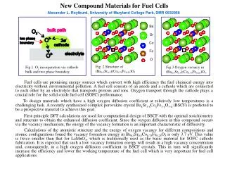
Strategies for the design of membranes for fuel cells. Ph. D Seminar – I M. Helen. Contents. Introduction Membranes in electrochemical devices Nafion ® – membrane of choice Modified PFSA membranes Alternate sulfonated polymer membranes Inorganic organic composite membranes

E N D
Strategies for the design of membranes for fuel cells Ph. D Seminar – I M. Helen
Contents • Introduction • Membranes in electrochemical devices • Nafion® – membrane of choice • Modified PFSA membranes • Alternate sulfonated polymer membranes • Inorganic organic composite membranes • Hybrid inorganic organic composite membranes • Acid-base polymer membranes • Concluding remark
Schematic representation of membrane and processes therein Pressure Reverse Osmosis Ultra filtration Micro filtration Electro Dialysis Membrane Potential Dialysis Concentration 1
Role of membrane • In reverse osmosis, ultra filtration, micro filtration & dialysis • To act as a molecular sieve • In electrochemical device • To separate anode and cathode • To prevent mixing of the fuel and oxidant • To provide a conductive pathway 2
Membranes in electrochemical devices • Fuel cells - Polymeric proton conducting membranes • Batteries - Lithium ion cells - Amorphous polyethylene oxide (PEO) • Water electrolysis - Bipolar ion exchange membranes • Sensor - Polymeric membranes • Biosensors – Lipid membranes, enzyme immobilized membranes 3
Required and desirable characteristics • High ionic conductivity (and zero electronic conductivity) • Long-term chemical stability at elevated temperatures in oxidizing and reducing environments • Stable under the fuel cell potential window • Good mechanical strength - resistance to swelling • Low oxidant and fuel cross-over • Low cost and ready availability 4
Nafion® x = 5-13.5; y = 1 m = 1; n =2 • Advantages • Stable in both oxidative and reductive environments • Excellent proton conductor ( 0.07 - 0.23 S cm-1at 100 % RH) 1M H2SO4 = 0.08 S cm-1 5
Simplified Nafion® structure according to water content Dry state of PFSA Water incorporated PFSA Fully swollen PFSA G. Gebel, Polymer41(2000) 5829 6
Characteristics of Nafion® membranes • Nafion xyzz’ • xy - Equivalent weight/100 • zz’- Thickness S. Slade et al.,J. Electrochem. Soc., 149 (2002) A1556 7
Characteristics of other commercial polymer membranes • General structure • A polymer containing anion groups(SO3-) on a polymer backbone or side chain (proton exchange membranes) 8
Limitations of Nafion® • Dehydrates at T > 80 oC & RH < 100% • Diffusion of other species • Lack of safety during its manufacturing and use • Expensive (~ 1000 $/m2) 9
Modified PFSA membranes • Thin and reinforced PFSA membranes • Swelling with low volatile and non aqueous solvents • Composites with hygroscopic oxides • Composites with solid inorganic proton conductors 10
Thin and reinforced PFSA membranes • To decrease the internal resistance • To reduce material cost • To improve water management Nafion with porous polypropylene/polysulfone • Thickness has been reduced to 5 - 30μm • Has good conductivity & mechanical properties • Water management is improved Drawback • Reduced mechanical strength (under high temp & swelling) B. Bae et al.,J. Membr. Sci., 202 (2002) 245 11
Swelling with low volatile and non aqueous solvents • Phosphoric acid (B.P: 158 °C) with Nafion achieved a conductivity of 0.05 S cm-1 at 150 °C • Acts as a Bronsted base & solvates the proton • Allows high operational temperature >100 °C • Imidazole (B.P: 255 °C) and benzimidazole (B.P: 360 °C) were also tried Limitations • No significant improvement in conductivity at low humidity • Imidazole groups are not as water in solvating membrane acid groups R. Savinell et al., J. Electrochem. Soc., 141 (1994) L46 12
Composites with hygroscopic oxides • SiO2 and TiO2 • Internal (self) humidification at low operational temperatures • Water uptake: • Pristine Nafion - 27 wt % • Nafion containing 3 wt % SiO2 - 43 wt % • Conductivity in the range of 10-7 to 10-3 S cm-1 at 100°C M. Watanabe et al.,J. Electrochem. Soc. 143 (1996) 3847 13
Composites with solid inorganic proton conductors • Bifunctional particles - both hydrophilic and proton conducting • Inorganic proton conductors • Heteropolyacids • zirconium phosphates • Decreases the chemical potential of water inside the membrane • Provides H-bonding sites for water • Increase in hydration of the membrane • Decrease in water transport and evaporation 14
Nafion/HPA Properties: • Increased conductivity than Nafion : 0.012 – 0.015 S cm-1 at 35 % RH • Water uptake: • Pristine Nafion - 27 wt % • Nafion/HPA - 95 wt % Drawbacks: • HPA is highly water soluble eventually leaches out from PEM • Decreased tensile strength (~14 kPa whereas Pristine Nafion ~ 40 MPa ) S. Malhotra et al.,J. Electrochem. Soc.144 (1997) L23 15
Nafion/α-ZrP Properties: • Water insoluble • Has intercalated hydronium ions with conductivity of 0.1 S cm-1 at 100 ºC at 100% RH • Enhanced performance is due to increased water retention capability • Replacement of unassociated pore water with hydrophilic α-ZrP nanoparticles • Capillary condensation effects due to the smaller dimensions of the free spaces in α-ZrP filled pores Drawbacks: • H+ transport properties depend upon humidity • Water management is difficult P. Costamagna et al.,Electrochim Acta47 (2002) 1023 16
Alternate sulfonated polymer membranes Fluoropolymers Aromatic polymers Polysiloxanes • To lower the material cost • To improve the operating temperature • Polymers should have high chemical and thermal stability 17
Fluoropolymers • Sulfonated polystyrenes - first generation polymer electrolytes for fuel cells • Suffers from a short lifetime • Partially fluorinated polymer • Poly(tetrafluoroethylene-hexafluoropropylene) (FEP) • Poly(vinylidene fluoride) (PVDF) • Prepared by grafting and then sulfonating the styrene groups • High water uptake & high proton conductivity S. Hietala et al.,Mater. Chem., 8 (1998) 1127 18
Polysiloxanes • Organic modified silicate electrolyte (ORMOLYTE) by using arylsulfonic anions or alkylsulfonic anions grafted to the benzyl group were attempted • Exhibit a proton conductivity of 10-2 S cm-1 at RT • Chemically and thermally stable up to 200 °C V. D. Noto et al.,Electrochimica Acta 50 (2005) 4007 19
Aromatic polymers • Cost effective and ready availability • Good oxidation resistance of aromatic hydrocarbons • Electrolyte for high temperature range ( > 100 ºC) • Investigated systems • polyetheretherketone (PEEK) • polysulfones (PSF) or Polyethersulfone (PES) • polybenzimidazoles (PBI) • polyimides (PI) • polyphenylenes (PP) • poly(4-phenoxybenzoyl-1,4-phenylene) (PPBP) 20
Sulfonation of polymers • By direct sulfonation in concentrated sulfuric acid, chlorosulfonic acid or sulfur trioxide • By lithiation-sulfonation-oxidation • By chemically grafting a group containing a sulfonic acid onto a polymer • By graft copolymerization using high energy radiation followed by sulfonation of the aromatic component • By synthesis from monomers bearing sulfonic acid groups 21
Modification of S-PEEK S-PEEK • Has excellent thermal oxidation resistance with a glass transition temperature of 143 °C • Conductivity, 100ºC= 8 x 10⁻³ S cm-1 at 100 % RH S-PEEK/SiO2 • S-PEEK containing 10 wt% SiO2 – Exhibited best mechanical and electrical characteristics (100ºC= 9 x 10⁻² S cm-1) S-PEEK/ZrO2 • S-PEEK containing 10 wt% ZrO2 – Exhibited low permeability and good conductivity ( 100ºC= 4.5 x 10⁻² S cm-1) S-PEEK/HPA • S-PEEK containing 60 wt% TPA – Increased glass transition temperature, humidity and conductivity ( 120ºC= 0.1S cm-1) 22
Microstructures Nafion 117 S-PEEK • Wide channels • More separated • Less branched • Small -SO3- /-SO3- separation • pKa -6 • DMeOH = 2.91 × 10⁻⁶ cm2/s • Narrow channels • Less separated • Highly branched • Large -SO3- /-SO3- separation • pKa -1 • DMeOH = 6.57 × 10⁻⁸ cm2/s K. D. Kreuer, J. Membr. Sci. 185 (2001) 29 23
Limitations of sulfonated polymers • Highly deliquescent • Hard to recover from solution • Has a temperature limit at 200 ºC • H+ conductivity decays due to decomposition of the SO3H groups • High sulfonation results in high swelling and therefore poor mechanical properties 24
Inorganic Organic composite membranes Justification: • To improve self-humidification of the membrane • To reduce the electro-osmotic drag • To suppress fuel crossover • To improve mechanical strength • To improve thermal stability • To enhance the proton conductivity 25
Organic component Inorganic component Perfluorosulfonic acid (PFSA) Poly-(ethylene oxide)s (PEO) Polybenzimidazole (PBI) Sulfonated polystyrene Sulfonated polysulfone (SPSF) Sulfonated polyetheretherketone (SPEEK) Oxides (Silica, titania & Zirconia) Inorganic proton conductors (zirconium phosphates, heteropolyacids, metal hydrogen sulfate) Requirement - Stability under fuel cell condition 26
Effect of adding an inorganic component to a polymer membrane • Thermodynamic changes due to hygroscopic nature • Changes in capillary forces and the vapour liquid equilibrium as a result of changes in the pore properties • Surface charge interactions between the composite species • Changes the morphology of the membrane 27
Zirconium phosphates α-Zr(HPO4)2·H2O • Exhibits H+ conductivity upto 300 ºC • Transport mechanism is dominated by surface transport than bulk γ (ZrPO4[O2P(OH)2]· nH2O) 28
Attempts to enhance the proton conductivity • Intercalation of functional groups • Composites α-ZrP membranes • External surface area maximization (mechanical and colloidal synthesis) • Internal surface area maximization (sol–gel synthesis and pillaring) 29
Intercalation of functional groups Layered ZrP and phosphonates (S cm-1) at 100ºC, 95% RH α-Zr(O3P-OH)2 . H2O * 1.8 × 10-5 γ-ZrPO4[O2P(OH)2]. 2H2O* 2 × 10-4 Zr(O3P-OH)2 . nH2O ¶ 1–5 x 10⁻³ Zr(O3P-OH)1.5(O3P-C6H4SO3H)0.5 ¶ 0.9–1.1 x 10⁻² Zr(O3P-OH)(O3P-C6H4SO3H) nH2O § 0.8–1.1 x 10⁻¹ * Crystalline; § Semicrystal: ¶ Amorphous 30
Composites α-ZrP membranes • s-PEK membrane (thickness 50 μm) • s-PEK filled with 35 wt% of Zr(O3P-OH)(O3P-C6H4SO3H).nH2O P. Costamagna et al.,Electrochimica Acta 47 (2002)1023 31
Heteropolyacids - H3PM12O40 • Exhibit high proton conductivities; • 0.18 S cm-1 for H3PW12O40.29H2O • 0.17 S cm-1 for H3PMo12O40.29H2O • Thermally stable at the temperatures of interest, < 200 °C • Greater water uptake, but decreased tensile strength than Nafion 117 • Water soluble – need to be immobilized S. Malhotra et al.,J. Electrochem. Soc. 144 (1997) L23 32
Proton transport in polymer/nano particle composite membranes Hydronium Water Nanoparticle • Increases the swelling of the membranes at lower relative humidity • Increases the resistance to fuel crossover • Increases the proton transport through the water phase and reduces methanol permeability 33
Hydrogen sulphates, MHSO4 M - Rb, Cs, or NH4+ • H-bonded solid acids with disordered phases show high conductivity • Upon slight heating changes to disordered structure • Proton transport is due to reorientation of SO4 groups in the disordered structure • Drawbacks • Water soluble • Poor mechanical strength • Volume expansion at raised temperatures • SO4 reduced under H2 atm 34
Proton transport mechanism in CsHSO4 • CsHSO4 consist of oxyanions, linked together through hydrogen bonds • At 141ºC it undergoes a “superprotonic” phase change (from monoclinic to tetragonal structure) • Undergoes rapid reorientation - time scale 10– 1 1 sec • Proton conductivity 10-2 S cm-1 S. M. Haile et al, Nature 410 (2001) 1589 35
Flexibility Organic PVA, PEG, GPTS Inorganic SiO2, ZrO2, TiO2 Stability Active Moiety POM Value adding Hybrid Organic Inorganic Composite membranes 36
Systems investigated • GPTS*–STA–SiO2 • GPTS–STA–ZrP • GPTS–SiO2, H+ conductivity 1 x 10⁻⁷ - 3.6 x 10⁻⁶ S cm-1 at 20 - 100ºC • GPTS–SiO2 with 30 wt% STA, H+ conductivity 1.4 x 10⁻³ – 1.9 x 10⁻² S cm-1 at 20 – 100ºC • GPTS–ZrP 30 wt% STA, H+ conductivity 2 x 10⁻² S cm-1 at 100ºC *3-glycidoxypropyltrimethoxysilane 37
Inorganic additives enhanced thermal stability and water uptake • The proton conducting path is through the pseudo-PEO network Y. Park et al.,Solid State Ionics145 (2001) 149 38
Acid-Base Polymer membranes • Two Approaches: • Basic polymer with excess acid • Acidic polymer with excess base (sulfonated polymer with absorbed imidazole, benzimidazole or another appropriate proton acceptor) Basic polymers Acids • Polybenzimidazole (PBI) • Poly-(ethylene oxide)s (PEO) • Polyvinyl alcohol (PVA) • Polyacrylamide (PAAM) • Polyethylenimine (PEI) • Nylon H3PO4 H2SO4 HCl HNO3 HClO4 39
Acid doped polybenzimidazole • High thermal and mechanical stability • Very low solvent permeability (electroosmotic drag ~ 0) + H2SO4, H3PO4 D. Jones et al.,J. Membr. Sci., 185 (2001) 41 40
Membrane Conductivity (S cm-1) PBI-S 4.2 x 10⁻⁴ PBI-S/NH4OH 1.5 x 10⁻² PBI-S/imidazole 7.9 x 10⁻³ PBI-S/LiOH 1.2 x 10⁻² PBI-S/NaOH 1.2 x 10⁻² PBI-S/KOH 1.7 x 10⁻² PBI-S/CsOH 1.7 x 10⁻² Doping with organic and inorganic bases N-benzylsulfonate grafted PBI J. Roziere et al, Solid State Ionics145 (2001) 61 41
Advantages • High temperature oxidative stability of the blank PBI (~300 ºC) • Good chemical stability and mechanical properties of the blank PBI • Exhibits good conductivity • Ease of fabrication of the composite • Less fuel cross-over than Nafion 117 Disadvantages • Long-term stability and reliability based on composite PBI membranes must be proven • Conductivity of PBI–H3PO4 is 10 times < Nafion 117 • Diffusion of H3PO4 out of the PBI limit membrane performance 42
Concluding remark Technology for the design of membranes for fuel cell applications is on the verge of a major breakthrough. How and when are the two questions awaiting answers. 43