Download
1 / 20
200 likes | 334 Views
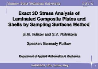
Non-Linear Piezoelectric Exact Geometry Solid-Shell Element Based on 9-Parameter Model Gennady M. Kulikov Department of Applied Mathematics & Mechanics. (1) (2). Laminated shell with embedded piezoelectric layer (PZT). + -. I.

E N D
Non-Linear Piezoelectric Exact Geometry Solid-Shell Element Based on 9-Parameter ModelGennady M. Kulikov Department of Applied Mathematics & Mechanics
(1) (2) Laminated shell with embedded piezoelectric layer (PZT) + - I h =z -z – shell thickness; u(q1,q2) – displacement vectors of S-surfaces (I = -, M, +) Shell Kinematics (Kulikov, 2001)
(3) (4) (5) eij (q1,q2) – Green-Lagrange strains of S-surfaces (I = -, M, +) I Representation of Displacement Vectors Strain-Displacement Equations (Kulikov & Carrera, 2008)
(6) Aa, ka – Lame coefficients and principal curvatures of reference surface Strain Parameters
(7) (8) (9) j(q1,q2) – electric potentials of outer surfaces of th piezoelectric layer (A = -, +) A Electric PotentialElectric Field
(10) (11) (12) –strain vector; () – stress vector; E()– electric field vector D() – electric displacement vector; A() , C()–elastic matrices d(), e() –piezoelectric matrices;(),()– dielectric matrices Constitutive Equations
Displacement-Independent Strains Hu-Washizu Variational Equation (13) (14) Stress Resultants
(15) Exact geometry piezoelectric solid-shell element based on 9-parameter model, where xa= (qa-da)/a – normalized curvilinear coordinates; 2a – element lengths
A A () () Duu , Duj , Djj – mechanical, piezoelectric and dielectric constitutive matrices pi – surface tractions; q – surface charge densities (A = -, +)
(16) (17) (18) Finite Element Formulation Displacement Interpolation Electric Potential Interpolation Assumed Natural Strain Method
(19) (20) uj() u Br, Br , Ar(U)– constant inside the element nodal matrices r r 1 2 00 01 01 01 10 10 10 aij = 0 except for aij = 1, a11 = a13 = a33 = a22 = a23 = a33 = 1 Assumed Electric Field Interpolation Displacement-Independent Strains Interpolation
(21) (22) KT– tangent stiffness matrix of order 3636; U – incremental displacement vector • Matrix KT is evaluated using analytical integration • No matrix inversion is needed to derive matrix KT • Use of extremely coarse meshes Stress Resultants Interpolation Finite Element Equations
1. Cantilever Plate with Segmented Actuators (geometrically linear solution)
M M M Bending w1 = u3 (B)/b for [30/30/0]s plate Twisting w2 = (u3(C)-u3(A))/b for [30/30/0]s plate
Deformed configuration of [0/45/-45]s plate at voltage j =1576 V NI – number of Newton iteration; RN = ||R ||- Euclidean norm of residual vector DN = ||UG- UG || - Euclidean norm of global displacement vectors [NI] [NI+1] [NI] 2. Cantilever Plate with Segmented Actuators (geometrically non-linear solution)
3. Spiral Actuator (PZT-5H) rmin = 1.875 mm, rmax = 15.2 mm, h = 0.2 mm L = 215 mm, b = 3.75 mm, Dj =100 V r = rmin + aq2 , q2[0, 8p]
a b c d r = 7.5 cm, R = 15 cm, L = 20 cm hC = 0.04 cm, hPZT = 0.01 cm, F = 200 N [90/0/90] graphite/epoxy shell Shell configurations at: (a) F = 0, j = 0; (b) F = 200 N, j = 0 (c) F = 200 N, j = 1000 V; (d) F = 200 N, j = 1960 V 4. Shape Control of Pinched Hyperbolic Shell
a b Midsurface displacements of hyperbolic shell at points A, B, C and D versus: (a) force F for j = 0, (b) voltage j for F = 200 N
a b Midsurface displacements of hyperbolic shell at points belonging to: (a) hyperbola BD and (b) hyperbola AC