Download
1 / 31
310 likes | 414 Views
Structures of the Energy flow system. Mechatronics 2007. Mekatronics - energiflow. Structures of the energy conversion system ( < 1 h) Primary energy to output Electrical as intermediate Power electronic converters as components ( < 3 h) AC/DC/AC Modulation

E N D
Structures of the Energy flow system Mechatronics 2007
Mekatronics - energiflow Structures of the energy conversion system (< 1 h) Primary energy to output Electrical as intermediate Power electronic converters as components (< 3 h) AC/DC/AC Modulation Power Units (50 Hz / SMPS / Integration) Passive components / Integration of passives Electromechanical converters as components (< 3 h) Conv. machine types Elektrostrictive/magnetostrictive converters Cooling Power and Energy density Energyconverters as construction elements (< 1 h) Laminated steel / powder pressing / injection moulding Powerelectronic measurements (< 2 h) Current / voltage / flux Torque /speed / position Preassure / flow (in pumps)
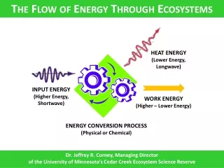
Energy processed in several steps Output energy Energy Process • Primary energy source • (chemical, mechanical, electrical) • Intermediate electrical energy storage • (capacitive, inductive, ...) • Output energy • (mechanical, heat, light, sound,...) Signal
Primary energy sources • Chemical • Batteries • fuel cell with hydrogen • Combustion • Capacitors • Electrical • Power grid • Mechanical • Flywheel • Solar power • Max 10…15% 1000 W/m2
Primary to intermediate energy conversion • AC to rectified DC • 230 V / 50 Hz to almost 325 V (singel phase rectifier) • 400 V / 50 Hz to almost 540 V (three phase rectifier) • AC to low voltage DC • Transformer + rectifier • Switched Mode Power Supply (SMPS) • DC to DC • Non-isolated, step down • Non-isolated, step up • Isolated
AC to rectified DC – 1 phase Ud • High harmonic content in the line current ud,i
AC to rectified DC – 3 phase Ud • High harmonic content in the line current ud,i
AC to low voltage DC • Step down transformer + rectifier. Still the same problem with high harmonics in the line current. • Galvanic isolation
SMPS – Switched Mode Power Supplies 2 Ud • Function • Transistor “on” -> increasing inductor current through transistor • Transistor off -> decreasing inductor current through diode • Advantages: • Output voltage greater than input voltage (universal input); • Simple control; • Input inductance acts like a filter toward AC line; • Many control ICs available on the market. • PFC of 0.95 or better over line and load variations. u 1 i u i
Switched mode power supplies for low voltage DC with flyback 2 1 • Features: • Galvanic isolation to the feeding grid • Output voltage range adjusted with the transformer ratio
Example from http://www.irf.com/technical-info/refdesigns/irismps4.pdf
Kvadranter + u - Kraft- elektronisk omvandlare i
1-quadrant step down converter (buck-converter) • Output voltage lower than input voltage • Output current positive
1-quadrant step up converter (boost-converter) id + L, R i Ud + + e u - - - • Output voltage higher than input voltage • Output current positive
Styrning av 1-kv. Uppsp.omv id + L, R i Ud + + e u - - - u i id
2-quadrant DC converter • Current can be negative • Both directions for energy flow • Voltage unipolar, current bipolar • Equivalent switch:
4-Quadrant DC converter • All combinations of voltage and current • AC-voltage • Both directions for energy flow
Drive circuits • All power transistors need a gate/base-driver to • Switch between on- and off-state • Turn off at over current • Provide galvanic isolation to the control circuitry • Example of separate driver • 600V and 1200V gate driver in a single IC for MOSFET and IGBTs • Multiple Configurations • Single high side • Half-bridge • 3 phase inverter driver • Up to +2.0/-2.0A output source/sink current enables fast switching • Integrated protection and feedback functions • Optional deadtime control • Tolerant to negative voltage transient • Up to 50V/ns dV/dt immunity • Optional soft turn-on • Uses low cost bootstrap power supply • CMOS and LSTTL input compatible
Fully integrated power semiconductors • Self-containing with built in: • Drive circuit • Protection circuit • Galvanic isolation • Power transistor
Passive components • Inductors • Capacitors • Heat sinks
Inductors • Many types: • Ferrite type components • For SMPS transformers @ 100 kHz • Chokes & Coils & Inductors • For EMC supression • Toroidal transformers • Laminated core transformers • Current transformers • Noise protection transformers • AC voltage stabilizers
Capacitors • Electrolytic • For energy storage and filtering • Film • For filtering • Must be selected with care, can be destroyed by: • Harmonic currents • Over voltages • Most producers have software design tools available on their home page.
Heat sinks • Extruded • Stacked fin • Water cooled • Integrated in housing
Power Electronic Design • All circuits contain capacitive and inductive elements with switches in between. • Non ideal components contribute to short circuit currents and over voltages that may harm/destroy the circuit. • Example: • Solution: - Minimize non ideal components and distances do instead look like this: What should look like this:
How to improve a circuit • Minimize length of capacitive cables • Example: • Avoid capacitance in inductive circuits • Eg. keep primary and secondary winding of a transformer apart.