Download
1 / 19
210 likes | 594 Views
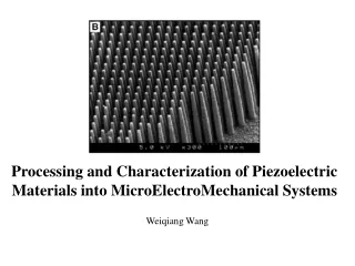
Piezoelectric Materials. Chris Petorak REU Dr. Bowman and J.Jones. Piezoelectric Materials. Below Curie Temp Perovskite unit cell Unit electric dipole Poling of dipoles in single direction allows for piezoelectric properties. Piezoelectric Properties.

E N D
Piezoelectric Materials Chris Petorak REU Dr. Bowman and J.Jones
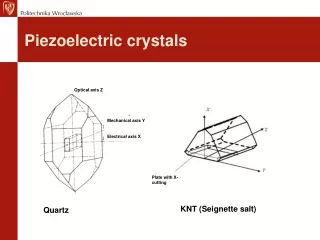
Piezoelectric Materials • Below Curie Temp • Perovskite unit cell • Unit electric dipole • Poling of dipoles in single direction allows for piezoelectric properties
Piezoelectric Properties • Apply an external stress = a voltage difference between top and bottom electrode • Applied Voltage = a strain in the direction of the applied electric field.
Common Applications • Sensors ex. Microphones and Hydrophones • Actuators • Ultrasound technology
Fatigue of Ferroelectric Properties • Narrowing of Hystersis loop • Decreasing switchable polarization and d33 • Increasing # of cycles leads to greater reduction in ferroelectric properties Zhang,N. Li,L. Gui,Z. Degredation of piezoelectric and dielectirc relaxation properties due to electric faitgue in PLZT ferroelectric capacitors
Domain Wall Pinning • Oxygen Vacancies • Results in Space Charge • Space Charge accumulate to pin domain walls • Reduce domain wall mobility • Therefore reducing switch able polarization
Electrical Loading Hystersis loop Apply alternating field 180 domain reorientation Parallel plate capacitor Lower Cost & Easier to find Parts Compressive Loading Stress vs. Strain Apply stress to get 1% deformation 90 domain reorientation Compressive jig setup highly sensitive and expensive Cycling Setup Considerations
High Voltage Electric field higher than Ec Closer to saturation the greater the fatigue Low Frequency More time for E to affect domains and difficult movement Domains become set = greater internal stresses to be overcome in reverse cycle Cycling Setup Considerations
Building the Setup • 1st Setup – DC power source 1.4kV/mm Sinusoidal oscillator 20Hz • 2nd Setup – AC power source 60Hz Tube transformer 1.4kV/mm Variac • Parallel plate capacitor setup under constant stress
10-15 5-10 0-5 Trouble Shooting • Calibration of variable autotransformer indirectly • Linear relationship is found • E = V/t
Geometry K181 Sample #71,72 Sample #33,44 Sample #3,5 K182 Sample #13,15
Initial Run Cycled at 1.4kV/mm • K181 t = .0848in d = .965in • Fail mode cracking • NO significant degradation of d33 • Early in cycling 10^4
Second Run Cycled 1.2kV/mm • K182 Fail t = .0839in d = .843in • K181 degrades t = .0848in d = .841in
Trouble Shooting • Time constraints K182 is abandoned to focus further on K181 • Current is candidate for Failure Ohms law I = V/R • Resistance is geometry dependent - longer length = higher R - smaller area = higher R
Last Run • Area Considerations • = R*A/t • E = V/t • E*t = I* *t/A • A increases so does I because is independent of geometry
Area and Current • Current Macrolevel – seems to support theory • Current Microlevel – current/unit area leaves a hole in argument. • Probability of defects in greater in larger Volume • Porosity
Recommendations • Cycle further samples Large A large t at 1.2kV/mm Small A large t at 1.4kV/mm • Establish relationship for sample’s R at low I and low V. Use this to predict the Current flow through at high voltage.