Download
1 / 40
410 likes | 717 Views
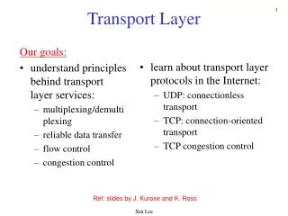
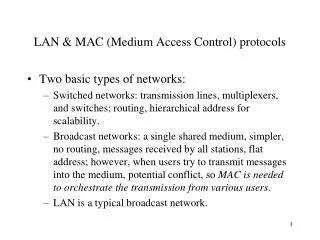
LAN & MAC (Medium Access Control) protocols. Two basic types of networks: Switched networks: transmission lines, multiplexers, and switches; routing, hierarchical address for scalability.

E N D
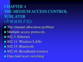
LAN & MAC (Medium Access Control) protocols • Two basic types of networks: • Switched networks: transmission lines, multiplexers, and switches; routing, hierarchical address for scalability. • Broadcast networks: a single shared medium, simpler, no routing, messages received by all stations, flat address; however, when users try to transmit messages into the medium, potential conflict, so MAC is needed to orchestrate the transmission from various users. • LAN is a typical broadcast network.
Peer-to-peer protocols VS. MAC • Both are to transfer user information despite transmission impairments • For peer-to-peer: • Main concern: loss, delay, resequencing • Using control frames to coordinate their actions • Delay-bandwidth is important • Involved only two peer processes • MAC: • Main concern: interference from users • Using some mechanisms to coordinate the access of channel • Delay-bandwidth is important • Need the coordination from all MAC entities, any one does not cooperate, the communication will not take place.
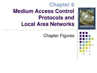
What are going to be discussed • Introduction to broadcast networks • Overview of LANs: frame format & placement in OSI. • Random access: ALOHA & CSMA-CD (Carrier Sensing Multiple Access with Collision Detection ) i.e., Ethernet. • Scheduling: token-ring. • LAN standards (brief view) • LAN bridges: used to connect several LANs.
Multiple access communications 3 2 4 1 Shared Multiple Access Medium 5 M • Any transmission from any station can be heard by any other stations • If two or more stations transmit at the same time, collision occurs Figure 6.1
Satellite communication involves sharing of uplink and downlink frequency bands = fin Satellite Channel = fout Figure 6.3
Cellular networks: radio shared by mobile users and require MAC BSS BSS MSC SS#7 STP HLR VLR wireline terminal EIR PSTN AC MSC = mobile switching center PSTN = public switched telephone network STP = signal transfer point VLR = visitor location register AC = authentication center BSS = base station subsystem EIR = equipment identity register HLR = home location register Figure 4.52
Multi-drop telephone line requires access control Multidrop telephone lines Inbound line Host Outbound line Terminals Figure 6.4
Ring networks and multi-tapped buses require MAC Ring networks Multitapped Bus Figure 6.5
Wireless LAN: share wireless medium and require MAC Figure 6.6
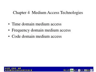
Approaches to sharing transmission medium Minimize the incidence of collision to achieve reasonable usage of medium. Good for bursty traffic. Medium Sharing Techniques Static Channelization Dynamic Medium Access Control Partitioned channels are dedicated to individual users, so no collision at all. Good for steady traffic and achieve efficient usage of channels Scheduling Random Access Try and error. if no collision, that is good, otherwise wait a random time, try again. Good for light traffic. Schedule a orderly access of medium. Good for heavier traffic. Figure 6.2
MAC and performance • Shared medium is the only means for stations to communicate • Some kind of MAC technique is needed • Like ARQs, which use ACK frame to coordinate the transmission and consume certain bandwidth, the MAC will need to transfer some coordination information which will consume certain bandwidth of shared medium. • Delay-bandwidth product plays a key role in the performance of MAC (as in ARQs).
Delay-bandwidth product and performance (suppose two station A and B want to transmit information) Distance d meters tprop = d / seconds A transmits at t = 0 A B B transmits before t = tprop and detectscollision shortly thereafter A B A detects collision at t = 2 tprop A B 1. : the speed of light, 3*108 meters/second 2. Before A begins to transmit, A listens to medium, if busy, wait; otherwise, do it (suppose t=0) 3. If B wants to transmit after t=tprop A’s transmission has reached B, so B waits and A captures medium successfully and transmits its entire message. 4. If B wants to transmit before t=tprop, it listens and no transmission is going on, so B begins to transmit, then collision occurs. B detects collision shortly, but A detects collision at t=2tprop 5. Therefore, 2tpropis required to coordinate the access for each packet transmitted. Figure 6.7
MAC efficiency • Suppose bit rate of medium is R, then number • of bits “wasted” in access coordination is 2tpropR. And suppose average length of packets is L. Then efficiency in use of the medium is: 1 L 1 Efficiency = = = tpropR • L + 2tpropR 1+2a 1 + 2 L a=tpropR / L i.e., the ratio of (one-way) delay-bandwidth product to the average packet length. Suppose a = 0.01, then efficiency = 1/1.02 = 0.98 a = 0.1, then efficiency = 1 / 2 = 0.50
Examples of efficiency • Ethernet (CSMA-CD): • Efficiency = 1/(1+6.44a) where a = tpropR/L. • Token-ring networks: • Efficiency = 1/(1+a’ ) where a’ = ring-latency in bits/L where ring-latency contains: • The sum of bit delays introduced at each ring adapter. • Delay-bandwidth product where delay is the time required for a bit to circulate around the ring.
Typical LAN structure and network interface card RAM RAM (a) A LAN connects servers, workstations, Printers, etc., together to achieve sharing • NIC is parallel with memory • but serial with network • 2. ROM stores the implementation of MAC • 3. Unique physical address burn into ROM • 4. A hardware in NIC recognizes physical, • broadcast & multicast addresses. • 5. NIC can be Set to “promiscuous” mode • to catch all transmissions. (b) Ethernet Processor ROM Figure 6.10
IEEE 802 LAN standards Network Layer Network Layer LLC 802.2 Logical Link Control Data Link Layer 802.11 Wireless LAN Other LANs 802.3 CSMA-CD 802.5 Token Ring MAC Physical Layer Various Physical Layers Physical Layer OSI IEEE 802 One LLC and several MACs, each MAC has an associated set of physical layers. MAC provides connectionless transfer. Generally no error control because of relatively error free. MAC protocol is to direct when they should transmit frames into shared medium. Figure 6.11
The MAC sublayer provides unreliable datagram service MAC MAC MAC PHY PHY PHY Unreliable Datagram Service Important: all three MAC entities must cooperate to provide datagram service, I.e., the interaction between MAC entities is not between pairs of peers, but rather all entities must monitor all frames. Figure 6.12
MAC MAC MAC PHY PHY PHY LLC provides three HDLC services: 1. Unacknowledged connectionless service, recall HDLC has unnumbered frames; 2. Reliable connection-oriented service in the form of HDLC ABM mode; 3. Acknowledged connectionless service, need to add two unnumbered frames to HDLC frame set. C A A C Reliable Packet Service LLC LLC LLC LLC can provide reliable packet transfer service Figure 6.13
LLC provides additional addressing, i.e., SAP (Service Access Point). Like PPP, LLC can • support several different network connections with different protocols at the same time. • Typical SAPs: IP: 06, IPX: E0, OSI packets: FE etc. • In practice, LLC SAP specifies in which buffer the NIC places the frame, thus allowing the • appropriate network protocol to retrieve the data. 1 byte 1 1 or 2 Destination SAP Address Source SAP Address Control Information Source SAP Address Destination SAP Address C/R I/G 1 7 bits 7 bits 1 I/G = Individual or group address C/R = Command or response frame LLC PDU structure and its support for several SAPs Figure 6.14
Header overhead: TCP, IP: >=20 LLC: 3 or 4 MAC: 26 TCP segments Reliable IP Header Unreliable IP Packet IP LLC PDU LLC Header Data Orderly MAC Header FCS Chaos MAC frame LLC PDU and MAC frame Figure 6.15
Random Access • Why random access? • Reaction time (i.e. 2 times of propagation delay) is very important for performance, e.g. in Stop-and-Wait, when reaction time is small (i.e. the ACK will arrive soon) the performance is very good, however, if reaction time is large, then performance is very bad. • Therefore, proceed the transmission without waiting for ACK and deal with collision/error after the fact, i.e. random access. • Three types of random accesses: • ALOHA, slotted ALOHA, and CSMA-CD
ALOHA • Basic idea: • let users transmit whenever they have data to be sent. • When collision occurs, wait a random time ( why? ) and retransmit again. • Differences between regular errors &collision • Regular errors only affect a single station • Collision affects more than one • The retransmission may collide again • Even the first bit of a frame overlaps with the last bit of a frame almost finished, then two frames are totally destroyed.
ALOHA random access scheme Suppose L: the average frame length, R: rate, X=L/R: frame time 1. Transmit a frame at t=t0 (and finish transmission of the frame at t0+X ) 2. If ACK does not come after t0+X+2tprop or hear collision, wait for random time: B 3. Retransmit the frame at t0+X+2tprop+B Two modes: collide only from time to time and snowball effect collision First transmission Retransmission t t0 t0+X t0-X t0+X+2tprop t0+X+2tprop Vulnerable period Backoff period: B Time-out Retransmission if necessary When collision occurs? Vulnerable period: t0-X to t0+X, (2X seconds) if any other frames are transmitted during the period, the collision will occur. Therefore the probability of a successful transmission is the probability that there is no additional transmissions in the vulnerable period. Figure 6.16
The performance of ALOHA • Let S be the arrival rate of new frames in units of frames/X seconds, • S is also the throughput of the system. • Let G be the total arrival rate in units of frames/X seconds, G • contains the new and retransmissions and is the total load. • Assume that aggregate arrival process resulting from new and • retransmitted frames has a Poisson distribution with an average • number of arrivals of 2G frames/2X seconds, i.e., (2G)k P[k transmissions in2X seconds] = e-2G , k=0,1,2,… k! Therefore, the throughput of the system is: S=G*P[no collision] =G*P[0 transmission in 2X seconds] (2G)0 e-2G =G e-2G =G* 0!
What results can be obtained from the graph? 1.peak value at G=0.5 with S=0.184 2.for any given S, there are two values of G, corresponding to the two modes: occasional collision mode with S G and frequent collision mode with G >> S 0.184 Ge-2G Throughput S versus load G for ALOHA Figure 6.17
Slotted ALOHA • Synchronize the transmissions of stations • All stations keep track of transmission time slots and are allowed to initiate transmissions only at the beginning of a time slot. • Suppose a packet occupies one time slot • Vulnerable period is from t0-X to t0, i.e., X seconds long. Therefore, the throughput of the system is: S=GP[no collision] =GP[0 transmission in X seconds] (G)0 =G e-G =G e-G 0!
Slotted ALOHA random access scheme t0=(k+1)X First transmission Retransmission t (k+1)X =nX kX t0+X+2tprop t0+X+2tprop Backoff period: B Time-out Retransmission if necessary Vulnerable period: t0-X to t0 , i.e., X seconds long Figure 6.16
Peak value at G=1 with S=0.368 for slotted ALOHA, double compared with ALOHA. In LAN, propagation delay may be negligible and uncoordinated access of shared medium is possible but at the expense of significant wastage due to collisions and at very low throughput. Throughput of ALOHAs is not sensitive to the reaction time because stations act independently. 0.368 Ge-G S 0.184 Ge-2G G Throughput S versus load G for ALOHA and slotted ALOHA Figure 6.17
CSMA (Carrier sensing multiple access) • Problem with ALOHAs: low throughput because the collision wastes transmission bandwidth. • Solution: avoid transmission that are certain to cause collision, that is CSMA. Any station listens to the medium, if there is some transmission going on the medium, it will postpone its transmission.
Suppose tprop is propagation delay from one extreme end to the other extreme end of the medium. Station A begins transmission at t=0 A Station A captures channel at t=tprop A When transmission is going on, a station can listen to the medium anddetect it. After tprop, A’s transmission will arrive the other end; every station will hear it and refrain from the transmission, so A captures the medium and can finish its transmission. But in ALOHAs, it is X or 2X Vulnerable period = tprop In LAN,generally, tprop < X sense sense sense sense CSMA random access scheme Figure 6.19
Three different CSMA schemes • Based on how to do when medium is busy: • 1-persistent CSMA • Non-persistent CSMA • p-persistent CSMA
1-persistent CSMA sense channel when want to transmit a packet, if channel is busy, then sense continuously, until the channel is idle, at this time, transmit the frame immediately. If more than one station are sensing, then they will begin transmission the same time when channel becomes idle, so collision. At this time, each station executes a backoff algorithm to wait for a random time, and then re-senses the channel again. Problem with 1-persistent CSMA is “high collision rate”.
Non-persistent CSMA sense channel when want to transmit a packet, if channel is idle, then transmit the packet immediately. If busy, run backoff algorithm immediately to wait a random time and then re-sense the channel again. Problem with non-persistent CSMA is that when the channel becomes idle from busy, there may be no one of waiting stations beginning the transmission, thus waste channel bandwidth,
p-persistent CSMA sense channel when want to transmit a packet, if channel is busy, then persist sensing the channel until the channel becomes idle. If the channel is idle, transmit the packet with probability of p, and wait, with probability of 1-p, additional propagation delay tprop and then re-sense again
Throughput versus load G for 1-persistent (three different a=tprop/X ) S 0.53 1-Persistent CSMA 0.01 0.45 0.16 0.1 G 1 Figure 6.21 - Part 2
Throughput versus load G for non-persistent (three different a=tprop/X ) S 0.81 Non-Persistent CSMA 0.01 0.51 0.14 0.1 G 1 1-persistent is sharper than non-persistent. a=tprop/X has import impact on the throughput. When a approaches 1, both 1-persistent and non-persistent is worse than ALOHAs. Figure 6.21 - Part 1
CSMA-CD • When the transmitting station detects a collision, it stops its transmission immediately, Not transmit the entire frame which is already in collision. • The time for transmitting station to detect a collision is 2tprop. • In detail: when a station wants to transmit a packet, it senses channel, if it is busy, use one of above three algorithms (i.e., 1-persistent, non-persistent, and p-persistent schemes). The transmitter senses the channel during transmission. If a collision occurred and was sensed, transmitter stops its left transmission of the current frame; moreover, a short jamming signal is transmitted to ensure other stations that a collision has occurred and backoff algorithm is used to schedule a future re-sensing time. • The implication: frame time X >= 2tprop, , since X=L/R, which means that there is a minimum limitation for frame length.
A begins to transmit at t=0 B A B begins to transmit at t= tprop- B detects collision at t= tprop B A A B A detects collision at t= 2 tprop- The reaction time in CSMA-CD is 2tprop It takes 2 tprop to find out if channel has been captured Figure 6.22
When a is small, i.e, tprop << X, the CSMA-CD is best and all CSMAs are • better than ALOHAs. • When a is approaching 1, CSMAs become worse than ALOHA. • ALOHAs are not sensitive to a because they do not depend on reaction time. CSMA/CD 1-P CSMA Non-P CSMA max Slotted Aloha Aloha a = tprop /X Maximum achievable throughput of random access schemes Figure 6.24
Summary of random access schemes (Continuous) ALOHA: try to send a frame anytime, if collision, wait random time, resend. Vulnerable period: 2X , maximum throughput: 0.184. Slotted ALOHA: send a frame at the beginning of a time slot. If collision, wait a random time to a new time slot, and resend again.Vulnerable period: X , maximum throughput: 0.368. 1-persistent CSMA: listen before transmission, if busy, continuously listen until channel become idle, then transmit immediately. If collision, wait a random time, re-listen. Vulnerable period: tprop , throughput: 0.53 for a=tprop/X=0.01 Non-persistent CSMA: listen before transmission, if busy, wait a random time, re-listen. if idle, transmit. If collision, wait a random time, re-listen. Vulnerable period: tprop , throughput: 0.81 for a=tprop/X=0.01 p-persistent CSMA: persist listening to the channel until idle. At this time, with probability p, transmit the packet, and with probability of 1-p, do not transmit but wait additional tprop and then re-listen. If collision, wait random time, re-listen. Vulnerable period: tpropthroughput dependent on p. CSMA-CD: using any one of above three.Listen during transmission. If collision, stop its transmission immediately.Vulnerable period: tprop.throughput: >0.90 for a=tprop/X=0.01 Important: a=tprop/X affects performance. Requirement: frame lengthcan not below certain value for given tprop, (the distance of LAN).