Download
1 / 86
880 likes | 1.32k Views
Medium Access Control for Wireless Links. CS 515 Mobile and Wireless Networking Ibrahim Korpeoglu Computer Engineering Department Bilkent University. Outline. What we have see so far? PHY layer functions and parameters General Wireless System Architecture Media Access Control

E N D
Medium Access Control for Wireless Links CS 515 Mobile and Wireless Networking Ibrahim Korpeoglu Computer Engineering Department Bilkent University
Outline • What we have see so far? PHY layer functions and parameters • General Wireless System Architecture • Media Access Control • Classes of MAC protocols • Simplex and Duplex Channels • Coordinated MAC Schemes • FDMA • TDMA • Capacity of TDMA systems and which factors affect the capacity. • Spread Spectrum Access Methods • FHMA • Case study: Bluetooth • CDMA • Hybrid Spread Spectrum Schemes. • Random MAC Schemes • CSMA • MACA and MACAW • Case Study: IEEE 802.11 MAC © Ibrahim Korpeoglu
What we have seen so far? • Physical layer functions • Get stream of bits and transport them to the other end. • Modulation/Demodulation • We have seen that this is not an easy task • Large-scale path loss and Small-scale fading and multipath effects causes the received power at the receiver to • Fluctuate (hard to decode the symbols (bits)) • To decrease (Affects of interfering sources increases) • Received signal power level affect the quality of the signals (information) that is transported. • Received signal power level defines the Signal-to-Noise (SNR) ratio © Ibrahim Korpeoglu
What we have seen so far? • We have seen • That SNR and bandwidth of a channel affects • Datarate – bps) of the wireless channel by Shannon limit • The bit error rate (BER) on the channel. • That multipath fading results in a wireless channel error model that changes states between good (low-error rate) and bad (high error-rate) • Large-scale path loss defines the range of stations for different environments (LOS, urban,…) • The above factors are important channel characteristics that affect the design of wireless systems architectures and design of the protocols and applications for wireless links/networks • In short, we have seen so far some of Fundamental Concepts of Wireless Communication. © Ibrahim Korpeoglu
What we will do now? • We will look now to the protocols, algorithms, schemes that are developed over this wireless channels. • How can we share a wireless channel: • Results in Wireless Media Access Control Protocols • How we can change base stations: Results in Handoff algorithms and protocols • How can we seamlessly support mobile applications over wireless links: • Results in mobility protocols like Mobile IP, Cellular IP, etc. • How can we design efficient transport protocols over wireless links: • Results in solutions like SNOOP, I-TCP, M-TCP, etc. • How different wireless networks/systems are designed? • Bluetooth, IEEE 802.11, GSM, etc. © Ibrahim Korpeoglu
Wireless System Architecture and Functions Applications TCP/IP Neighbor Discovery and Registration, Multicasting, Power Saving Modes, Address Translation (IP-MAC), Routing, Quality of Services, Subnet Security Wireless Subnet Controller Medium Access Control, MAC level Scheduling, Link Layer Queueing, Link Layer Reliability – ACKs, NACKs, …. Wireless Link Layer (Layers 1 and 2 in ISO/OSI Network Reference Model) Link Controller Transceiver Frame Controller Framing and frame synchronization, error control, CRC, bit scrambling, widening, …. Carrier frequency, channel bandwidth, carrier detect, Captude detect, channel data rate, modulation, Received signal strength (RSSI), transmit power, Power control, … Physical Radio © Ibrahim Korpeoglu
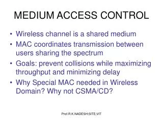
Medium Access Control • Wireless spectrum (frequency band) is a very precious and limited resource. • We need to use this resource very efficiently • We also want our wireless system to have high user capacity • A lot of (multiple) users should be able to use the system at the same time. • For these reasons most of the time, multiple users (or stations, computers, devices) need to share the wireless channel that is allocated and used by a system. • The algorithms and protocols that enables this sharing by multiple users and controls/coordinates the access to the wireless channel (medium) from different users are called MEDIUM ACCESS, or MEDIA ACCESS or MULTIPLE ACCESS protocols, techniques, schemes, etc…) © Ibrahim Korpeoglu
Wireless Media Access Control • Random Schemes (Less-Coordinated) • Examples: MACA, MACAW, Aloha, 802.11 MAC,… • More suited for wireless networks that are designed to carry data: IEEE 802.11 Wireless LANs • Coordinated Schemes • Examples: TDMA, FDMA, CDMA • More suited for wireless networks that are designed to carry voice: GSM, AMPS, IS-95,… • Polling based Schemes • Examples: Bluetooth, BlueSky,… • Access is coordinated by a central node • Suitable for Systems that wants low-power, aims to carry voice and data at the same time. © Ibrahim Korpeoglu
Duplexing • It is sharing the media between two parties. • If the communication between two parties is one way, the it is called simplex communication. • If the communication between two parties is two- way, then it is called duplex communication. • Simplex communication is achieved by default by using a single wireless channel (frequency band) to transmit from sender to receiver. • Duplex communication achieved by: • Time Division (TDD) • Frequency Division (FDD) • Some other method like a random access method © Ibrahim Korpeoglu
Duplexing • Usually the two parties that want to communication in a duplex manner (both send and receive) are: • A mobile station • A base station • Two famous methods for duplexing in cellular systems are: • TDD: Time Division Duplex • FDD: Frequency Division Duplex © Ibrahim Korpeoglu
Duplexing - FDD F • A duplex channel consists of two simplex channel with different carrier frequencies • Forward band: carries traffic from base to mobile • Reverse band: carries traffic from mobile to base M B R Base Station Mobile Station Reverse Channel Forward Channel frequency fc,,F fc,R Frequency separation Frequency separation should be carefully decided Frequency separation is constant © Ibrahim Korpeoglu
Duplexing - TDD • A single radio channel (carrier frequency) is shared in time in a deterministic manner. • The time is slotted with fixed slot length (sec) • Some slots are used for forward channel (traffic from base to mobile) • Some slots are used for reverse channel (traffic from mobile to base) M B Mobile Station Base Station Slot number 0 1 2 3 4 5 6 7 … F R F R F R F R …. channel Reverse Channel Forward Channel time Ti+1 Ti Time separation © Ibrahim Korpeoglu
Duplexing – TDD versus FDD • FDD • FDD is used in radio systems that can allocate individual radio frequencies for each user. • For example analog systems: AMPS • In FDD channels are allocated by a base station. • A channel for a mobile is allocated dynamically • All channels that a base station will use are allocated usually statically. • More suitable for wide-area cellular networks: GSM, AMPS all use FDD • TDD • Can only be used in digital wireless systems (digital modulation). • Requires rigid timing and synchronization • Mostly used in short-range and fixed wireless systems so that propagation delay between base and mobile do not change much with respect to location of the mobile. • Such as cordless phones… © Ibrahim Korpeoglu
Multiple Access - Coordinated • We will look now sharing the media by more than two users. • Three major multiple access schemes • Time Division Multiple Access (TDMA) • Could be used in narrowband or wideband systems • Frequency Division Multiple Access (FDMA) • Usually used narrowband systems • Code Division Multiple Access • Used in wideband systems. © Ibrahim Korpeoglu
Narrow- and Wideband Systems • Narrowband System • The channel bandwidth (frequency band allocated for the channel is small) • More precisely, the channel bandwidth is large compared to the coherence bandwidth of the channel (remember that coherence bandwidth is related with reciprocal of the delay spread of multipath channel) • AMPS is a narrowband system (channel bandwidth is 30kHz in one-way) • Wideband Systems • The channel bandwidth is large • More precisely, the channel bandwidth is much larger that the coherence bandwidth of the multipath channel. • A large number of users can access the same channel (frequency band) at the same time. © Ibrahim Korpeoglu
Narrowband Systems • Could be employing one of the following multiple access and duplexing schems • FDMA/FDD • TDMA/FDD • TDMA/TDD • Wideband systems • Could be employing of the following multiple access and duplexing schemes • TDMA/FDD • TDMA/TDD • CDMA/FDDCDMA/TDD © Ibrahim Korpeoglu
Cellular Systems and MAC © Ibrahim Korpeoglu
Frequency Division Multiple Access B • Individual radio channels are assigned to individual users • Each user is allocated a frequency band (channel) • During this time, no other user can share the channel • Base station allocates channels to the users fN,F f1,F f2,F f2,R f1,R fN,R … M M M © Ibrahim Korpeoglu
Features of FDMA • An FDMA channel carries one phone circuit at a time • If channel allocated to a user is idle, then it is not used by someone else: waste of resource. • Mobile and base can transmit and receive simultaneously • Bandwidth of FDMA channels are relatively low. • Symbol time is usually larger (low data rate) than the delay spread of the multipath channel (implies that inter-symbol interference is low) • Lower complexity systems that TDMA systems. © Ibrahim Korpeoglu
Capacity of FDMA Systems Frequency spectrum allocated for FDMA system … Guard Band channel Guard Band Bt : Total spectrum allocation Bguard: Guard band allocated at the edge of the spectrum band Bc : Bandwidth of a channel AMPS has 12.MHz simplex spectrum band, 10Khz guard band, 30kHz channel bandwidth (simplex): Number of channels is 416. © Ibrahim Korpeoglu
Time Division Multiple Access • The allocated radio spectrum for the system is divided into time slots • In each slot a user can transmit or receive • A user occupiess a cyclically repeating slots. • A channel is logically defined as a particular time slot that repeats with some period. • TDMA systems buffer the data, until its turn (time slot) comes to transmit. • This is called buffer-and-burst method. • Requires digital modulation © Ibrahim Korpeoglu
TDMA Concept Downstream Traffic: Forward Channels: (from base to mobiles) 1 2 3 … N 1 2 3 …. N … Logical forward channel to a mobile Base station broadcasts to mobiles on each slot Upstream Traffic: Reverse Channels: (from mobile to base) 1 2 3 … N 1 2 3 …. N … Logical reverse channel from a mobile A mobile transmits to the base station in its allocated slot Upstream and downstream traffic uses of the two different carrier frequencies. © Ibrahim Korpeoglu
TDMA Frames • Multiple, fixed number of slots are put together into a frame. • A frame repeats. • In TDMA/TDD: half of the slots in the frame is used for forward channels, the other is used for reverse channels. • In TDMA/FDD: a different carrier frequency is used for a reverse or forward • Different frames travel in each carrier frequency in different directions (from mobile to base and vice versa). • Each frame contains the time slots either for reverse channels or forward channel depending on the direction of the frame. © Ibrahim Korpeoglu
General Frame and Time Slot Structure in TDMA Systems One TDMA Frame Preamble Information Trail Bits Slot 1 Slot 2 Slot 3 … Slot N Guard Bits Sync Bits Control Bits Information CRC One TDMA Slot A Frame repeats in time © Ibrahim Korpeoglu
A TDMA Frame • Preamble contains address and synchronization info to identify base station and mobiles to each other • Guard times are used to allow synchronization of the receivers between different slots and frames • Different mobiles may have different propagation delays to a base station because of different distances. © Ibrahim Korpeoglu
Efficiency of a Frame/TDMA-System • Each frame contains overhead bits and data bits. • Efficiency of frame is defined as the percentage of data (information) bits to the total frame size in bits. bT: total number of bits in a frame Tf: frame duration (seconds) bOH: number of overhead bits Number of channels in a TDMA cell: m: maximum number of TDMA users supported in a radio channel © Ibrahim Korpeoglu
TDMA • TDMA Efficiency • GSM: 30% overhead • DECT: 30% overhead • IS-54: 20% overhead. • TDMA is usually combined with FDMA • Neighboring cells be allocated and using different carrier frequencies (FDMA). Inside a cell TDMA can be used. Cells may be re-using the same frequency if they are far from each-other. • There may be more than one carrier frequency (radio channel) allocated and used inside each cell. Each carrier frequency (radio channel) may be using TDMA to further multiplex more user (i.e. having TDMA logical channels inside radio channels) • For example: GSM uses multiple radio channels per cell site. Each radio channel has 200KHz bandwidth and has 8 time slots (8 logical channels). Hence GSM is using FHMA combined with TDMA. © Ibrahim Korpeoglu
Contemporary TDMA Systems © Ibrahim Korpeoglu
Features of TDMA • Enables the sharing of a single radio channel among N users • Requires high data-rate per radio channel to support N users simultaneously. • High data-rate on a radio channel with fixed bandwidth requires adaptive equalizers to be used in multipath environments (remember the RSM delay spread s parameter) • Transmission occurs in bursts (not continues) • Enables power saving by going to sleep modes in unrelated slots • Discontinues transmission also enables mobile assisted handoff • Requires synchronization of the receivers. • Need guard bits, sync bits. large overhead per slot. • Allocation of slots to mobile users should not be uniform. • It may depend on the traffic requirement of mobiles. • This brings extra flexibility and efficiency compared to FDMA systems. © Ibrahim Korpeoglu
Capacity of TDMA Systems • Capacity can be expressed as • System Capacity (the capacity of the overall system covering a region) • Depends on: • Range of cells • Whether the system can support macro-cells, micro-cells or pico-cells. • Cell Capacity • Depends on the radio link performance between a base-sation and mobiles: • The lowest C/I (carrier-to-interence) ratio the system can operate for example quality of transmission. This in turn depends on the speech coding technique, desired speech quality, etc. • Data-rate over the channel which dependsmodulation efficiency (bits_per_second/Hz) and channel bandwidth. • The frequency re-use factor © Ibrahim Korpeoglu
System Capacity: Cluster: 7 cells constitute a cluster. Cluster size = 7 C B A y B D x A G G E A z F Frequency reuse factor is 1/7: same frequency is used every 7 cell. A is one set of frequencies, B is an other, etc. A mobile in cell x receives carrier signal from base x and interferences from base stations at cells y and z. The carrier signal strength of all combined signal strengthfrom interfering base stations is called C/I or S/I ratio. © Ibrahim Korpeoglu
C/I affect on capacity • C/I ratio affects the cluster size, hence the frequency reuse factor. • Frequency_reuse_factor = 1 / cluster_size • Cluster size can be 3, 7, 12, 13, … • Cluster size affects the cell capacity • (it affects the maximum number of frequencies that can be used in a cell) • A low C/I requirement for appropriate quality enables smaller cluster sizes, hence larger frequency reuse factor, meaning that larger cell capacities © Ibrahim Korpeoglu
AMPS Parameters Channel bandwidth = 30Khz Required C/I: 18 dB Frequency re-use factor: 1/7 (cluster size=7) Required bandwidth per user = 30kHz. GSM Parameters Channel banwidth: 200 KHz Required bandwidth per user = 200/8 = 25 Khz. Required minimum C/I: 9dB Frequency re-use factor: 1/3 (cluster size=3) Comparing Systems © Ibrahim Korpeoglu
Spread Spectrum Access • SSMA uses signals that have transmission bandwidth that is several orders of magnitued larger than minimum required RF bandwidth. • Provides • Immunity to multipath interference • Robust multiple access. • Two techniques • Frequency Hopped Multiple Access (FHMA) • Direct Sequence Multiple Access (DSMA) • Also called Code Division Multiple Access – CDMA © Ibrahim Korpeoglu
Frequency Hopping (FHMA) • Digital muliple access technique • A wideband radio channel is used. • Same wideband spectrum is used • The carrier frequency of users are varied in a pseudo-random fashion. • Each user is using a narrowband channel (spectrum) at a specific instance of time. • The random change in frequency make the change of using the same narrowband channel very low. • The sender receiver change frequency (calling hopping) using the same pseudo-random sequence, hence they are synchronized. • Rate of hopping versus Symbol rate • If hopping rate is greather: Called Fast Frequency Hopping • One bit transmitted in multiple hops. • If symbol rate is greater: Called Slow Frequency Hopping • Multiple bits are transmitted in a hopping period • GSM and Bluetooth are example systems © Ibrahim Korpeoglu
Case Study - Bluetooth • Uses Frequency Hopping in cell (piconet) over a 79 MHz wideband radio channel. • Uses 79 narrowband channels (carrier frequencies) to hop through. • Freq (f) = 2402+k MHz, k = 0,...,78 • Channel spacing is 1 MHz (narrowband channel bandwidth) • Wideband spectrum width = 79 MHz. • Hopping Rate = 1600 Hops/Second • Hopping sequence is determined by Bluetooth Hardware address and Clocks that are syncrozied between sender and receiver 79 MHZ 0 1 2 3 ..... 77 78 79-Hop System 1 MHZ A hop sequence could be: 7,1,78,67,0, 56,39,....... © Ibrahim Korpeoglu
Case Study: Bluetooth – Piconet and FHSS Each node is classified as master or slave. Master defines a piconet (a cell). Maximum 7 slaves can be connected to a master. Master coordinates access to the the media. All traffic has to go over master. Slaves can not talk to each-other directly. Picocell S Range = 10m Raw Data-rate: 1 Mbps/piconet Radio channel used by devices in a piconet is 79MHz channel, which Is frequency hopped: hopping though 789 channels. Hoprate = 1600 hops/sec FHSS M S S All slaves and the master hops according to the same hopping sequence. The hopping sequence is determined by the clock and BT_address of the master. © Ibrahim Korpeoglu
Case Study: Bluetooth – Scatternet and FHSS Piconet S S Piconet can be combined into scatternets. Red slave acts as a bridge between two piconets. M2 Piconet S FHSS S FHSS M1 Each piconet uses FHSS with different hopping sequences (masters are different). This prevents interference between piconets. S S © Ibrahim Korpeoglu
Case Study: Bluetooth - Media access in a piconet Inside a piconet, access to the frequency hopped radio channel is coordinated using time division multiple access: TDMA/TDD. Slot duration = 1/1600 sec = 625ms Piconet S1 FHSS M In an even slot, master transmits to a slave. In an odd slot, the slave that is addressed in the previous master-to-slave slot transmits. S3 S2 0 1 2 3 4 5 6 7 ….. M-S1 S1-M M-S2 S2-M M-S3 S3-M M-S1 S1-M …… slot time=625ms © Ibrahim Korpeoglu
Code Division Multiple Access (CDMA) • In CDMA, the narrowband message signal is multiplied by a very large bandwidth signal called spreading signal (code) before modulation and transmission over the air. This is called spreading. • CDMA is also called DSSS (Direct Sequence Spread Spectrum). DSSS is a more general term. • Message consists of symbols • Has symbol period and hence, symbol rate • Spreading signal (code) consists of chips • Has Chip period and and hence, chip rate • Spreading signal use a pseudo-noise (PN) sequence (a pseudo-random sequence) • PN sequence is called a codeword • Each user has its own cordword • Codewords are orthogonal. (low autocorrelation) • Chip rate is oder of magnitude larger than the symbol rate. • The receiver correlator distinguishes the senders signal by examining the wideband signal with the same time-synchronized spreading code • The sent signal is recovered by despreading process at the receiver. © Ibrahim Korpeoglu
CDMA Advantages • Low power spectral density. • Signal is spread over a larger frequency band • Other systems suffer less from the transmitter • Interference limited operation • All frequency spectrum is used • Privacy • The codeword is known only between the sender and receiver. Hence other users can not decode the messages that are in transit • Reduction of multipath affects by using a larger spectrum • Random access possible • Users can start their transmission at any time • Cell capacity is not concerete fixed like in TDMA or FDMA systems. Has soft capacity • Higher capacity than TDMA and FDMA • No frequency management • No equalizers needed • No guard time needed • Enables soft handoff © Ibrahim Korpeoglu
CDMA Principle Represent bit 1 with +1 Represent bit 0 with -1 One bit period (symbol period) 1 1 Data 0 PN-Code (codeword) 1 1 1 0 1 0 1 1 1 1 1 0 1 0 1 1 Coded Signal Chip period Input to the modulator (phase modulation) © Ibrahim Korpeoglu
Processing Gain • Main parameter of CDMA is the processing gain that is defined as: Gp: processing gain Bspread: PN code rate Bchip: Chip rate R: Data rate • IS-95 System (Narrowband CDMA) has a gain of 64. Other systems have gain between 10 and 100. • 1.228 Mhz chipping rate • 1.25 MHz spread bandwidth © Ibrahim Korpeoglu
Near Far Problem and Power Control B pr(M) • At a receiver, the signals may come from various (multiple sources. • The strongest signal usually captures the modulator. The other signals are considered as noise • Each source may have different distances to the base station • In CDMA, we want a base station to receive CDMA coded signals from various mobile users at the same time. • Therefore the receiver power at the base station for all mobile users should be close to eacother. • This requires power control at the mobiles. • Power Control: Base station monitors the RSSI values from different mobiles and then sends power change commands to the mobiles over a forward channel. The mobiles then adjust their transmit power. M M M M © Ibrahim Korpeoglu
DSSS Transmitter Baseband BPF sss(t) Message + m(t) Transmitted Signal p(t) PN Code Generator Oscillator fc Chip Clock © Ibrahim Korpeoglu
DSSS Receiver Phase Shift Keying Demodulator IF Wideband Filter Received Data Received DSSS Signal at IF Synchronization System PN Code Generator © Ibrahim Korpeoglu
Spectra of Received Signal Spectral Density Spectral Density Interference Signal Interference Signal Frequency Frequency Output of Correlator after dispreading, Input to Demodulator Output of Wideband filter © Ibrahim Korpeoglu
CDMA Example (*) R Receiver (a base station) Data=1011… Data=0010… A B Transmitter Transmitter (a mobile) Codeword=101010 Codeword=010011 Data transmitted from A and B is multiplexed using CDMA and codewords. The Receiver de-multiplexes the data using dispreading. (*) This example is adapted from the CDMA example of Prof. Randy Katz at UC-Berkeley. © Ibrahim Korpeoglu
CDMA Example – transmission from two sources 1 0 1 1 A Data 0 1 0 0 1 1 0 1 0 0 1 1 0 1 0 0 1 1 0 1 0 0 1 1 A Codeword 1 0 1 1 0 0 0 1 0 0 1 1 1 0 1 1 0 0 1 0 1 1 0 0 A Signal 0 0 1 0 B Data 1 0 1 0 1 0 1 0 1 0 1 0 1 0 1 0 1 0 1 0 1 0 1 0 B Codeword 1 0 1 0 1 0 0 1 0 1 0 1 1 0 1 0 1 0 1 0 1 0 1 0 B Signal Transmitted A+B Signal © Ibrahim Korpeoglu
CDMA Example – recovering signal A at the receiver A+B Signal received A Codeword at receiver Integrator Output Comparator Output 0 1 0 1 Take the inverse of this to obtain A © Ibrahim Korpeoglu