Download
1 / 23
230 likes | 368 Views
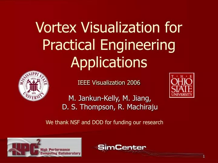
Vortex Visualization for Practical Engineering Applications IEEE Visualization 2006. M. Jankun-Kelly, M. Jiang, D. S. Thompson, R. Machiraju. We thank NSF and DOD for funding our research. Overview. Goal: Feature Based Vortex Visualization Challenge: Practical Engineering Data

E N D
Vortex Visualization for Practical Engineering ApplicationsIEEE Visualization 2006 M. Jankun-Kelly, M. Jiang, D. S. Thompson, R. Machiraju We thank NSF and DOD for funding our research
Overview • Goal: Feature Based Vortex Visualization • Challenge: Practical Engineering Data • Existing Techniques • Our Method • Results & Conclusions • Ongoing Work
Feature Based Vortex Visualization • Vortex: a swirling flow feature • Characterization: high level feature description Vortex visualization schematic: wing (green),vortex core line with sense of rotation (twisted ribbon), vortex extent & local tangential velocity (shaded surface)
Practical Engineering Data • large • unstructured mesh • low level • noisy • complex vortical flows • resolution spinning missile with dithering canards [Blades & Marcum 2004] serrated wing [Hammons 2006]
Existing Techniques • Region Based • Vorticity magnitude • Swirl parameter [Berdahl & Thompson 1993] • λ2 [Jeong & Hussain 1995] swirl parameter isosurfacing • Line Based • Sujudi & Haimes method (line segments) 1995 • streamlines from critical points • Banks & Singer method 1995 • Jiang’s combinatorial method 2002 • Sahner/Weinkauf/Hege λ2 and scalar field method 2005 core line segments [Sujudi & Haimes 1995] • Feature Based • Stegmeier et al. 2005 • Garth, Laramee, Tricoche et al. 2005 • Tricoche et al. 2005 streamlines
Overview of Our Method • Vortex detection • Topology Identification • Core line extraction • Extent computation Characteristics are found in stages 3,4. 1 2 3 4
Stage 1: Vortex Detection • Vortex detection • Topology Identification • Core line extraction • Extent computation Characteristics are found in stages 3,4. 1 2 3 4
Vortex DetectionLocal Extrema Method (LEM) Scalar field whose extrema coincide with vortex core lines Detection of line-type local extrema Vortex core candidate cells
Vortex Detection: Aggregation low level data (candidate cells) high level data (aggregates) Aggregation moves the level of abstraction from mesh data towards feature data.
Stage 2: Topology Identification • Vortex detection • TopologyIdentification • Core line extraction • Extent computation Characteristics are found in stages 3,4. 1 2 3 4
Topology Identification N vortices per aggregate, branching Aggregates are split into non-branching pieces with a k-means clustering algorithm. 1 vortex per aggregate, no branching (feature level data)
Stage 3: Core Line Extraction • Vortex detection • Topology Identification • Core line extraction • Extent computation Characteristics are found in stages 3,4. 1 2 3 4
Core Line Extraction The correction step locates the extreme value at the core line in the swirl plane. One core line is extracted from each aggregate with prediction / correction.
Correction Step: Function Fitting • Goal: locate extreme value in the swirl plane • 2D conical fitting function, one extreme value expected • Best fit: minimal standard deviation of fit error (red high, blue low) • Locate vortex core line with subcell resolution known function sample point local extremum (not a data point) predicted local extremum
Stage 4: Extent Computation • Vortex detection • Topology Identification • Core line extraction • Extent computation Characteristics are found in stages 3,4. 1 2 3 4
Vortex Extent Dacles-Mariani 1995 vortex core lines extent is the surface of maximum tangential velocity vortex extent surfaces
Feature Based Visualization: Serrated Wing • Extent: purple surface • Core lines: ribbons • Rotation sense: ribbon twist • Circulation: ribbon color visualization result visualization goal schematic
Timing on Sun UltraSPARC III (12 min on Apple XServe G5)
Conclusions • Vortex core lines resolved through novel function fitting technique • Individual vortices identified with novel k-means technique • These techniques work on practical data: large, noisy, unstructured, not ideally sampled • Feature based visualization of interesting, complex vortex behavior made possible
Ongoing Work • Improve Core Line Quality • reduce swirl vector field noise • improve local extremum detection • repair C0 discontinuities • Improve Extent Quality • local repair of outliers • better extent model
Questions? Monika Jankun-Kelly mjk@erc.msstate.edu