Download
1 / 64
640 likes | 818 Views
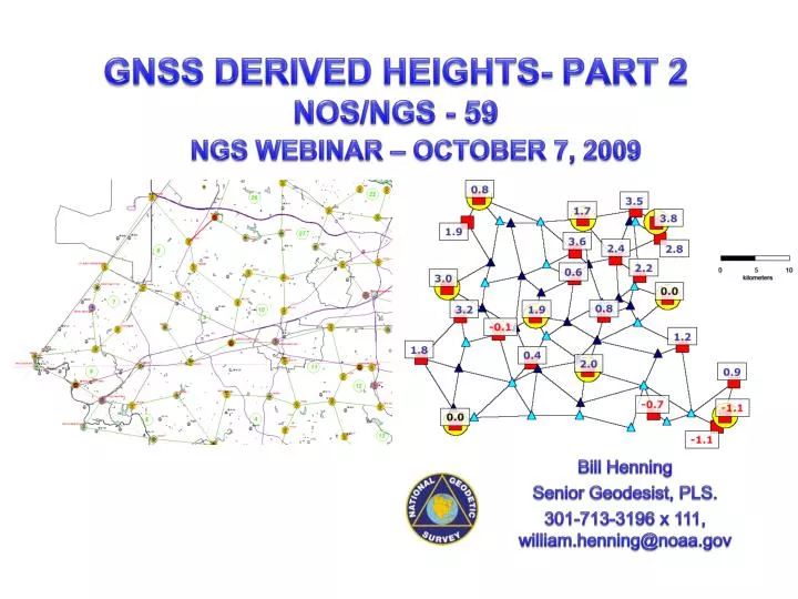
GNSS DERIVED HEIGHTS- PART 2 NOS/NGS - 59. NGS WEBINAR – OCTOBER 7, 2009. Bill Henning Senior Geodesist, PLS. 301-713-3196 x 111, william.henning@noaa.gov. GNSS DERIVED HEIGHTS. DAY 1 HT MOD GNSS HT METHODS NOS/NGS-58. DAY 2 NOS/NGS-59- Baltimore County and Fairfax County

E N D
GNSS DERIVED HEIGHTS- PART 2NOS/NGS - 59 NGS WEBINAR – OCTOBER 7, 2009 Bill Henning Senior Geodesist, PLS. 301-713-3196 x 111, william.henning@noaa.gov
GNSS DERIVED HEIGHTS DAY 1 • HT MOD • GNSS HT METHODS • NOS/NGS-58 DAY 2 • NOS/NGS-59- Baltimore County and Fairfax County • REAL TIME HT ISSUES
http://www.ngs.noaa.gov/ “NGS 58” “NGS 59”
ELLIPSOID, GEOID & ORTHO HEIGHTS H88= h83 – N09 “h = H + N” Earth’s Surface P Plumb Line Ellipsoid h Q N Mean Sea Level “Geoid” PO Ocean h (Ellipsoid Height) = Distance along ellipsoid normal (Q to P) N (Geoid Height) = Distance along ellipsoid normal (Q to PO) H (Orthometric Height) = Distance along plumb line (PO to P)
Expected Height Accuracies • GPS-Derived Ellipsoid Heights • 2 centimeters (following NOS NGS-58 Guidelines) • Geoid Heights (GEOID03) • Relative differences typically less than 1 cm in 10 km • 2.4 cm RMS about the mean nationally • 0.5 cm error in 10 Km • Leveling-Derived Heights • Less than 1 cm in 10 km for third-order leveling
Available “On-Line” at the NGS Web Site: www.ngs.noaa.gov SEARCH: “NGS 58”
What has been accomplished using NGS 58? • Control recovery, campaign planning/logistics • Obsschedulules, equipment checks • Observations: Repeat base lines Different days Different times of day (“15 hours, 27 hours”) (Detect, remove, reduce effects due to multipath and using the same satellite geometry)
Vector Processing Accomplished • Elevation Mask - 15 degrees • Ephemeris - Precise (typ. 14 days latency) • Tropospheric Correction Model • Iono Corrections - All baselines longer than 5 km. • Fix IntegersBaselines less than 5 km: L1 fixed solutionBaselines greater than 5 km: Iono free (L3) solution • Baselines must have RMS values ≤ 1.5 cm • Baselines must have difference in “up” ellipsoid height ≤ 2.0 cm
Repeat Vector Analysis After Re-Processing From To Session dh Diff Dist RMS Solution Station Station Meters cm Meters Type BM20 04KU 076G 46.0093628 0.015 L1 fixed double 077G 46.004 0.5 0.017 L1 fixed double 078R* 46.007 0.2 0.015L1 fixed double ZINC PT14 078A 15.397 3173 0.006 L1 fixed double 077A 15.400 0.3 0.006 L1 fixed double 076A 15.408 1.1 0.006 L1 fixed double TIDE 04KU 078G 43.680 3133 0.022 L1 fixed double 077R* 43.654 2.6 0.024 L1 fixed double 076R* 43.658 2.2 0.020 L1 fixed double PT14 TIDE 077A -55.031 3765 0.022 L1 fixed double 078R* -55.027 0.4 0.023 L1 fixed double 076R* -55.019 1.2 0.018 L1 fixed double 04KU 5144 078G 28.939 7250 0.014 Iono free fixed 077G 28.947 -0.8 0.014 Iono free fixed 076G 28.940 -0.1 0.020 Iono free fixed 5144 ZINC 078A -33.045 6167 0.011 Iono free fixed 077A -33.051 -0.6 0.009 Iono free fixed 076A -33.063 -1.8 0.013 Iono free fixed *NOTE - Reprocessed vectors which had differences greater than 2 cm.
Adjustment Procedures to Obtain • GPS-Derived NAVD’88 • Orthometric Heights
Least Squares Adjustments • The adjustment minimizes the effects of random errors • A least squares adjustment computes a single network solution, even with redundant vectors • Least squares will highlight blunders and large errors • It will provide estimates on the precision of the coordinates for the stations
GPS ELLIPSOID HEIGHT HIERARCHY HARN/Control Stations (75 km) Primary Base (40 km) Secondary Base (15 km) Local Network Stations (7 to 10 km)
Project Adjustment Following Guidelines 38°20’N CORS HARN NAVD’88 BM New Station Spacing Station Primary Base Station LATITUDE 8.2km 37°50’N 122°35’W 121°40’W LONGITUDE
Adjustment of Primary Network Stations From Control Horizontal Adjustment (Latitude, Longitude, Ellipsoid Heights) • Minimum Constrained [One fixed station] • Fix latitude, longitude and ellipsoid height at one station • Resolve all blunders and large residuals • Determine which Control and known Primary Base Station coordinates should be fixed • Constrained [All suitable stations fixed] • Fix latitude, longitude, and ellipsoid heights at Control and known Primary Base Stations • Make sure the constraints did not distort the project NOTE - Geoid model NOT applied at this time
Adjustment of Primary Base Stations Constrained Horizontally 38°20’N CORS HARN NAVD’88 BM New Station D191 10CC 19.0km Primary Base Station 28.7km 25.7km LATITUDE 38.3km 31.6km 38.7km 25.8km LAKE MART 29.6km MOLA 37°50’N 122°35’W 121°40’W LONGITUDE • CORS, Control Points (known Primary Control) horizontal • latitude, longitude, and ellipsoid heights • No NAVD88 orthometric heights constrained at this time
Adjustment of Local Network Stations Horizontal Adjustment (Latitude, Longitude, Ellipsoid Heights) • Minimum Constrained [One fixed station] • Fix latitude, longitude and ellipsoid height at one station • Resolve all blunders and large residuals • Evaluate coordinates at Control and Primary Base Station • should not be greatly affected by Local Station baselines • Constrained [All suitable stations fixed] • Fix latitude, longitude, and ellipsoid heights at Control and Primary Base Stations • Make sure the constraints did not distort the project NOTE - Geoid model NOT applied at this time
Adjustment of Local Network Stations Constrained Horizontally CORS HARN NAVD’88 BM New Station Spacing Station 38°16’N Primary Base Station LATITUDE 8.2km 37°55’N 121°40’W 122°20’W LONGITUDE • Existing and newly derived Primary Control horizontal • latitude, longitude, and ellipsoid heights • No NAVD88 orthometric heights constrained at this time
Combined Network Horizontal Adjustment • Perform combined adjustment • Control and Primary Base network along with local network • Latitude, longitude, and ellipsoid height • Use GEOID model to obtain geoid heights • Make sure combined adjustment did not distort the project
38°20’N CORS HARN NAVD’88 BM New Station Constrained Horizontally Spacing Station Primary Base Station LATITUDE 8.2km 37°50’N 122°35’W 121°40’W LONGITUDE Combined Horizontal Adjustment • CORS, Control Points and existing and new Primary Control horizontal • latitude, longitude, and ellipsoid heights • No NAVD88 orthometric heights constrained at this time
Repeat Vector Analysis From To Session dh Diff Dist RMS Solution Station Station Meters cm Meters Type BM20 04KU 078G 45.974* 3628 0.016 L1 float double 077G 46.004 -3.0 0.017 L1 fixed double 076G 46.009 -3.5 0.015 L1 fixed double ZINC PT14 078A 15.397 3173 0.006 L1 fixed double 077A 15.400 0.3 0.006 L1 fixed double 076A 15.408 1.1 0.006 L1 fixed double TIDE 04KU 078G 43.680 3133 0.022 L1 fixed double 077G 43.654*2.60.024 L1 fixed double 076G 43.607* 7.30.020 L1 fixed double PT14 TIDE 078A -54.703* 3765 0.047 L1 fixed double 077A -55.031 -32.80.022 L1 fixed double 076A -55.007*-30.4 0.019 L1 fixed double 04KU 5144 078G 28.939 7250 0.014 Iono free fixed 077G 28.947 -0.8 0.014 Iono free fixed 076G 28.940 -0.1 0.020 Iono free fixed 5144 ZINC 078A -33.045 6167 0.011 Iono free fixed 077A -33.051 -0.6 0.009 Iono free fixed 076A -33.063 -1.8 0.013 Iono free fixed *NOTE - Reprocess all vectors which have difference greater than 2 cm.
Guidelines for Establishing GPS-Derived Orthometric Heights (Standards: 2 cm and 5 cm) http://www.ngs.noaa.gov/ SEARCH: “NGS 59”
A Guide for Establishing GPS-Derived Orthometric Heights(Standards: 2 cm and 5 cm) • Three Basic Rules • Four Basic Control Requirements • Five Basic Procedures 3-4-5 System
Three Basic Rules • Rule 1: • Follow NGS’ guidelines for establishing GPS-derived ellipsoid heights (NGS 58:Standards: 2 cm and 5 cm) • Rule 2: • Use latest National Geoid Model, i.e., GEOID09 • Rule 3: • Use latest National Vertical Datum, i.e., NAVD 88
FOUR BASIC CONTROL REQUIREMENTS • BCR-1: Occupy stations with known NAVD 88 orthometric heights • Stations should be evenly distributed throughout project • BCR-2: Project areas less than 20 km on a side, surround project with NAVD 88 bench marks • i.e., minimum number of stations is four; one in each corner of project • BCR-3: Project areas greater than 20 km on a side, keep distances between GPS-occupied NAVD 88 bench marks to less than 20 km • BCR-4: Projects located in mountainous regions, occupy bench marks at base and summit of mountains, even if distance is less than 20 km
BCR Example BCR1: Sketch indicates that the 20 km rule was met. BCR2: This requirement is not applicable because the project is greater than 20 km on a side. BCR3: Circled bench marks are mandatory. Analysis must indicate bench marks have valid NAVD 88 heights. Other BMs can be substituted but user must adhere to 20 km requirement. BCR4: This requirement is not applicable because project is not in a mountainous region.
Five Basic Procedures • BP-1: Perform 3-D minimum-constraint least squares adjustment of GPS survey project • Constrain 1 latitude, 1 longitude, 1 orthometric height(Recall that ellipsoid heights have already been analyzed and adjusted) • BP-2: Analyze adjustment results from BP-1 • Detect and remove all data outliers
After performing minimum constraint adjustment, plot ellipsoid height residuals (or dU residuals) and investigate all residuals greater than 2 cm.
Station pairs with large residuals, i.e., greater than 2.5 cm, also have large repeat base line differences. NGS guidelines for estimating GPS-derived ellipsoid heights require user to re-observe these base lines. Following NGS guidelines provides enough redundancy for adjustment process to detect outliers and apply residual on appropriate observation, i.e., the bad vector.
Five Basic Procedures(continued) • BP-3: Compute differences between GPS-derived orthometric heights from minimum-constraint adjustment in BP-2 and published NAVD88 orthometric heights for all known bench marks
CONTROL COMPARISON OUTLIERS? PASSIVE CONTROL QUALITY (OVER TIME) GEOID MODEL QUALITY
GPS-Derived Orthometric Heights Minus NAVD88 Heights Geoid99 Units = Centimeters All height differences are under 5 cm and most are less than 2 cm. Almost all relative height differences between adjacent station pairs are less than 2 cm. However, most of the height differences appear to be positive relative to the southwest corner of the project.
Five Basic Procedures(continued) • BP-4: Determine which BMs have valid NAVD88 height values from results from BP-3 • Differences need to agree 2 cm for 2 cm survey • Differences need to agree 5 cm for 5 cm survey • May detect systematic tilt over large areas • Solve for geoidal slope and scale • BP-5: Perform constrained adjustment with results from BP-4 • Constrain 1 latitude, 1 longitude, all valid orthometric height values • Ensure final heights not distorted in adjustment
GPS-Derived Orthometric Heights Minus NAVD88 Heights Geoid99 Units = Centimeters To detect and remove any systematic trend, a tilted plane is best fit to the height differences (Vincenty 1987, Zilkoski and Hothem 1989). After a trend has been removed, all the differences are less than +/- 2 cm except for one and almost all relative differences between adjacent stations are less than 2 cm.
GPS-Derived Orthometric Heights Minus NAVD88 Heights Geoid99 Units = Centimeters After rejecting the largest height difference (-2.4 cm), of all the closely spaced station pairs only 3 are greater than 2 cm, 1 is greater than 2.5 cm and none are greater than 3 cm.
The red stars are the CORS used in the "Height Mod" projects. The stations in blue designated as "Height Mod" in the NGS Integrated Database
Identified as Height Mod survey station Elevation published to centimeters Orthometric height determined by GPS
D E C Topography B F A Hh-N h Hh-N h Hh-N h Hh-N h h Hh-N Hh-N h Ellipsoid N N N N N N GEOID03 = Published NAVD88 Orthometric Height = New Control GPS-Derived Heights from GEOID03 Separation
D E C Topography B F A h H h HGPS H h h HGPS h H h H Ellipsoid hadj hadj hadj hadj hadj hadj Adjusted Ellipsoid N N N N N N GEOID03 GEOID03 Geoid based on Ortho Heights = Published NAVD88 Orthometric Height = New Control Constrained Vertical Adjustment Ellipsoid Height Adjusted to Fit Constrained Orthometric Heights GPS-Derived Orthometric Heights
Combined Network Vertical Adjustment 3-D Vertical Adjustment (Orthometric Heights) • Minimum Constrained [One fixed station] • Fix latitude, longitude, and orthometric height at one station • Resolve all blunders and large residuals • Compare orthometric heights from adjustment with published NAVD 88 • Determine which NAVD 88 bench marks should be fixed • Constrained [All suitable orthometric heights fixed] • Fix latitude, longitude at one station • Fix orthometric heights at all suitable stations • Make sure the constraints did not distort the project
Minimally Constrained Vertical Adjustment 38°20’N Constrained Vertically CORS HARN NAVD’88 BM New Station Spacing Station Primary Base Station LATITUDE 8.2km 37°50’N 122°35’W 121°40’W LONGITUDE 1 horizontal latitude and longitude 1 NAVD88 orthometric heights
Constrained Vertical Adjustment 38°20’N Constrained Vertically CORS HARN NAVD’88 BM New Station Spacing Station Primary Base Station LATITUDE 8.2km 37°50’N 122°35’W 121°40’W LONGITUDE 1 horizontal latitude and longitude All valid NAVD88 orthometric heights
NGS Data Sheet - GEOID03 Published NAVD88 to GPS Derived h - N H = -(-32.60) 69.78 102.431 = 102.431102.38 102.429! GEOID 09 GEOID96 = 0.17 m GEOID99 = 0.11 m GEOID03 = 0.05 m GEOID 09 = 0.002 m
SUMMARY • Mistakes and systematic errors must be removed before the adjustment • A least squares adjustment handles random errors and provides a single solution (Try to eliminate all systematic errors) • The Minimally Constrained adjustment checks the internal consistency of the network • The Constrained adjustment checks the existing control and references the network to the datum • The vertical adjustment estimates GPS-derived Orthometric heights- Approaching 3rd order leveling accuracies