Download
1 / 24
240 likes | 480 Views
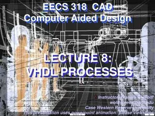
EECS 318 CAD Computer Aided Design. LECTURE 8: VHDL PROCESSES. Instructor: Francis G. Wolff wolff@eecs.cwru.edu Case Western Reserve University This presentation uses powerpoint animation: please viewshow. 2-to-1 Multiplexor: and Datapath multiplexor. a b. 0 1. a b. n. 0 1. Y. Y.

E N D
EECS 318 CADComputer Aided Design LECTURE 8: VHDL PROCESSES Instructor: Francis G. Wolff wolff@eecs.cwru.edu Case Western Reserve University This presentation uses powerpoint animation: please viewshow CWRU EECS 318
2-to-1 Multiplexor: and Datapath multiplexor a b 0 1 a b n 0 1 Y Y n n S S Datapath is n bits wide behavioral WITH s SELECT Y <= a WHEN ‘0’, b WHENOTHERS; WITH s SELECT Y <= a WHEN ‘0’, b WHENOTHERS; Where is the difference? CWRU EECS 318
Generic 2-to-1 Datapath Multiplexor Entity a b 0 1 n Y n n S LIBRARY IEEE; USE IEEE.std_logic_1164.all; USE IEEE.std_logic_arith.all; ENTITY Generic_Mux IS GENERIC (n: INTEGER); PORT (Y: OUT std_logic_vector(n-1 downto 0); a: IN std_logic_vector(n-1 downto 0); b: IN std_logic_vector(n-1 downto 0); S: IN std_logic_vector(0 downto 0) ); END ENTITY; CWRU EECS 318
Generic 2-to-1 Datapath Multiplexor Architecture ARCHITECTURE Generic_Mux_arch OF Generic_Mux IS BEGIN WITH S SELECT Y <= a WHEN "1",b WHEN OTHERS; END ARCHITECTURE; CONFIGURATION Generic_Mux_cfg OF Generic_Mux IS FOR Generic_Mux_arch END FOR; END CONFIGURATION; Configurations are require for simulation CWRU EECS 318
Structural SR Flip-Flop (Latch) NANDRSQn+10 0 U0 1 11 0 01 1 Qn R Q Q S ENTITY Latch ISPORT(R, S: IN std_logic; Q, NQ: OUT std_logic);END ENTITY; ARCHITECTURE latch_arch OF Latch ISBEGIN Q <= R NAND NQ;NQ <= S NAND Q;END ARCHITECTURE; CWRU EECS 318
Inferring Behavioral Latches: Asynchronous Sensitivity list of signals:Every time a change of state or event occurs on these signals this process will be called NANDRSQn+10 0 U0 1 11 0 01 1 Qn SequentialStatements R Q Q S ARCHITECTURE Latch2_arch OF Latch ISBEGINPROCESS (R, S) BEGINIF R= ‘0’ THEN Q <= ‘1’; NQ<=‘0’;ELSIF S=‘0’ THEN Q <= ‘0’; NQ<=‘1’;END IF; END PROCESS;END ARCHITECTURE; CWRU EECS 318
Gated-Clock SR Flip-Flop (Latch Enable) S Q LE Q R ARCHITECTURE Latch_arch OF GC_Latch IS BEGINPROCESS (R, S, LE) BEGIN IF LE=‘1’ THENIF R= ‘0’ THEN Q <= ‘1’; NQ<=‘0’;ELSIF S=‘0’ THEN Q <= ‘0’; NQ<=‘1’;END IF; END IF; END PROCESS;END ARCHITECTURE; CWRU EECS 318
Inferring D-Flip Flops: Synchronous Notice the Process does not contain D:PROCESS(Clock, D) Clock’EVENT is what distinguishes a D-FlipFlip from a Latch ARCHITECTURE Dff_arch OF Dff ISBEGIN PROCESS (Clock)BEGIN IF Clock’EVENT AND Clock=‘1’ THEN Q <= D; END IF; END PROCESS;END ARCHITECTURE; Sensitivity lists contain signals used in conditionals (i.e. IF) CWRU EECS 318
Inferring D-Flip Flops: rising_edge Alternate andmore readable way is to use the rising_edge function ARCHITECTURE Dff_arch OF Dff IS BEGINPROCESS (Clock)BEGIN IF Clock’EVENT AND Clock=‘1’ THEN Q <= D; END IF; END PROCESS;END ARCHITECTURE; ARCHITECTURE dff_arch OF dff IS BEGINPROCESS (Clock)BEGIN IF rising_edge(Clock) THEN Q <= D; END IF; END PROCESS;END ARCHITECTURE; CWRU EECS 318
Inferring D-Flip Flops: Asynchronous Reset ARCHITECTURE dff_reset_arch OF dff_reset IS BEGINPROCESS (Clock, Reset)BEGIN IF Reset= ‘1’ THEN -- Asynchronous ResetQ <= ‘0’ ELSIF rising_edge(Clock) THEN--Synchronous Q <= D; END IF; END PROCESS; END ARCHITECTURE; CWRU EECS 318
Inferring D-Flip Flops: Synchronous Reset PROCESS (Clock, Reset)BEGIN IF rising_edge(Clock) THEN IF Reset=‘1’ THENQ <= ‘0’ ELSE Q <= D; END IF; END IF;END PROCESS; Synchronous Reset Synchronous FF PROCESS (Clock, Reset)BEGIN IF Reset=‘1’ THENQ <= ‘0’ ELSIF rising_edge(Clock) THEN Q <= D; END IF;END PROCESS; Asynchronous Reset Synchronous FF CWRU EECS 318
D-Flip Flops: Asynchronous Reset & Preset PROCESS (Clock, Reset, Preset)BEGIN IF Reset=‘1’ THEN --highest priorityQ <= ‘0’; ELSIF Preset=‘1’ THENQ <= ‘0’;ELSIF rising_edge(Clock) THEN Q <= D; END IF; END PROCESS; CWRU EECS 318
RTL Multi-cycle Datapath: with controller Register Transfer Level (RTL) View CWRU EECS 318
CPU controller: Finite State Machine ALUzero PCWriteCond PCSourceMux PCWriteEnable PCWrite ALUOp MemRead ALUSrcAMux MemWrite ALUSrcBMux FSM IorDMux RegWrite IRWrite RegDstMux MemtoReg Clock Reset IRopcode CWRU EECS 318
CPU Controller: Entity ENTITY cpu_controller is PORT( CLK, RST :IN std_logic; IRopcode :IN std_logic_vector(5 downto 0); ALUzero :IN std_logic; PCWriteEnable :OUT std_logic; PCSourceMux :OUT std_logic_vector(1 downto 0); MemRead, MemWrite :OUT std_logic; IorDMux :OUT std_logic;IRWrite :OUT std_logic; RegWrite :OUT std_logic; RegDstMux :OUT std_logic; MemtoRegMux :OUT std_logic; ALUOp :OUT std_logic_vector(2 downto 0) ALUSrcAMux :OUT std_logic; ALUSrcBMux :OUT std_logic_vector(1 downto 0); ); END ENTITY; CWRU EECS 318
CPU controller: R-Format State Machine Cycle 1 Cycle 2 Cycle 3 Cycle 4 Decode Clock=1 Ifetch Reg/Dec Exec Wr R-Format Fetch Clock=1 Clock=1 Clock=1 ExecRtype WriteRtype CWRU EECS 318
CPU Controller: Current State Process ARCHITECTURE cpu_controller_arch OF cpu_controller IS TYPE CPUStates IS (Fetch, Decode, ExecRtype, WriteRtype); SIGNAL State, NextState :CPUStates; BEGIN PROCESS (State) BEGIN CASE State IS WHEN Fetch => NextState <= Decode; WHEN Decode => NextState <= ExecRtype; WHEN ExecRtype => NextState <= WriteRtype; WHEN WriteRtype => NextState <= Fetch; WHEN OTHERS => NextState <= Fetch; END CASE; END PROCESS; • • • CWRU EECS 318
CPU controller: NextState Clock Process PROCESS (CLK, RST) BEGIN IF RST='1' THEN -- Asynchronous Reset State <= Fetch; ELSIF rising_edge(CLK) THEN State <= NextState; END IF; END PROCESS; END ARCHITECTURE; CWRU EECS 318
T1 Fetch: State machine Cycle 1 Cycle 2 Cycle 3 Cycle 4 Decode Ifetch Reg/Dec Exec Wr R-Format Write Reg Exec Start MemRead=1, MemWrite=0IorD=1 (MemAddrPC)IRWrite=1 (IRMem[PC])ALUOP=ADD (PC4+PC)ALUSrcA=0 (=PC)ALUSrcB=1 (=4)PCWrite=1, PCSource=1 (=ALU)RegWrite=0, RegDst=X, MemtoReg=X Instruction Fetch CWRU EECS 318
T1 Fetch: VHDL with Moore Output States 'D' for Don’t Care MemRead=1, MemWrite=0IorD=1 (MemAddrPC)IRWrite=1 (IRMem[PC])ALUOP=ADD (PC4+PC)ALUSrcA=0 (=PC)ALUSrcB=1 (=4)PCWrite=1, PCSource=1 (=ALU)RegWrite=0, RegDst=X, MemtoReg=X PROCESS (State) BEGIN CASE State IS WHEN Fetch => NextState <= Decode; MemRead <= '1';MemWrite <= '0'; IorD <= '1' IRWrite <= '1'; ALUOp <= "010”; --add ALUSrcAMux <= '1'; --PC ALUSrcBMux <= "01"; --4 PCWriteEnable<= '1'; PCSourceMux <= "00"; --ALU (not ALUOut) RegWrite <= '0'; RegDstMux <= 'D'; MemtoReg <= 'D'; Instruction Fetch CWRU EECS 318
VHDL inferred Latches: WARNING In VHDL case statement The same signal must be defined for each case Otherwise that signal will be inferred as a latch and not as combinatorial logic! For example, Even though RegDstMux <= 'D' is not used and was removed from the Decode state This will result in a RegDstMux being inferred as latch not as logic even though in the WriteRtype state it is set CWRU EECS 318
Assignment #3: CPU Architecture design (1/3) Cyber Dynamics Corporation (18144 El Camino Real, S’Vale California) needs the following embedded model 101 microprocessor designed by Thursday October 5, 2000 with the following specifications • 16 bit instruction memory using ROM • 8 bit data memory using RAM • There are eight 8-bit registers • The instruction set is as follows • All Arithmetic and logical instructions set a Zero one-bit flag (Z) based on ALU result • add, adc, sub, sbc set the Carry/Borrow one-bit Flag (C) based on ALU result CWRU EECS 318
Assignment #3: CPU Architecture design (2/3) Arithmetic and logical instructionsadd $rt,$rs #$rt = $rt +$rs; C=ALUcarry; Z=$rt adc $rt, $rs #$rt = $rt +$rs+C; C=ALUcarry; Z; sub $rt, $rs #$rt = $rt - $rs; C=ALUborrow; Z; sub $rt, $rs #$rt = $rt - $rs - borrow; C; Z; and $rt, $rs #$rt = $rt & $rs; C=0; Z=$rt; or $rt, $rs #$rt = $rt | $rs; C=0; Z=$rt; xor $rt, $rs #$rt = $rt ^ $rs; C=1; Z=$rt;Other Instructions continued):lbi $r, immed #$r = immediate lbr $rt,$rs #$rt = Mem[$rs] lb $r, address #$r = Mem[address] stb $r, address #Mem[address]=$r bz address #if zero then pc=pc+2+addr bc address #if carry then pc=pc+2+addr j address #pc = address jr $r #pc = $r CWRU EECS 318
Assignment #3: CPU Architecture design (2/3) (1a) Design an RTL diagram of the model 101 processor and (1b) Opcode formats and (1c) Opcode bits of a Harvard Architecture CPU (determine your own field sizes). (1d) What is the size of the Program Counter? (2) Write the assembly code for a 32 bit add Z=X+Y located in memory address for @X = 0x80 @Y = 0x84 and @Z=0x88 (3) Draw the state diagram for your FSM controller (4) Write the VHDL code for the FSM controller Note: this will be part of your final project report CWRU EECS 318