1 / 0

EMS1EP Lecture 2 Electronic Circuits

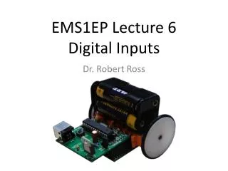
EMS1EP Lecture 2 Electronic Circuits. Dr. Robert Ross. Overview (what you should learn today). Ohms law Voltage/Current/Resistance Analog /Digital Breadboards. Voltage/Current/Resistance. Three important quantities in electronics Related by Ohms Law: V = I x R V: Voltage (Volts)

alban
Download Presentation

EMS1EP Lecture 2 Electronic Circuits

An Image/Link below is provided (as is) to download presentation Download Policy: Content on the Website is provided to you AS IS for your information and personal use and may not be sold / licensed / shared on other websites without getting consent from its author. Content is provided to you AS IS for your information and personal use only. Download presentation by click this link. While downloading, if for some reason you are not able to download a presentation, the publisher may have deleted the file from their server. During download, if you can't get a presentation, the file might be deleted by the publisher.

E N D

Presentation Transcript


  1. EMS1EP Lecture 2Electronic Circuits

    Dr. Robert Ross
  2. Overview (what you should learn today) Ohms law Voltage/Current/Resistance Analog/Digital Breadboards
  3. Voltage/Current/Resistance Three important quantities in electronics Related by Ohms Law: V = I x R V: Voltage (Volts) I: Current (Amps) R: Resistance (Ohms) How many Amps flow through this circuit?
  4. Hydraulics Analogy These quantities are based on electrons which are very small and hard to see A nice (but not perfect) analogy can be made with a closed hydraulic system sand filter Images from: http://hyperphysics.phy-astr.gsu.edu/hbase/electric/watcir.html
  5. Voltage Measured in Volts (V) Is the ‘electric potential’ between two points “Voltage is the work done per unit charge against a static electric field to move a charge between two points” Common sources: Power supply, battery, power point Like the water pressure in the hydraulics analogy (this is supplied by a water pump)
  6. Current Measured in Amps (I) Is the flow of electric charge through a circuit Typically the flow of electrons through a wire Like a the water pump in the hydraulics analogy which provides water pressure DC (Direct Current): Current only flows in one direction AC (Alternating Current): Current changes direction at a determined frequency For Hydraulics analogy – like the flow-rate More water flowing through pipe = higher flow-rate More electrons flowing through circuit = higher current
  7. Resistance Measured in Ohms (Ω) Opposition to the passage of current flowing through a conductor Wire has low resistance so it is a good conductor We use resistors to introduce resistance of a defined amount into a circuit e.g. to limit the current to an LED to control the brightness Hydraulics analogy – Sand filter decreases water flow
  8. Resistor colour codes The colours printed on the sides of the resistors specify the value What would the following resistors be:
  9. Review A circuit therefore has: Different voltages between different points Current flowing through it (pushed on by the voltage) Resistances which restrict the flow of current These are all related by Ohms law Image from: http://www.sengpielaudio.com/calculator-ohmslaw.htm
  10. Analog/Digital Common perception: Digital is all about 0’s and 1’s Analog is something different not using 0’s and 1’s In electronics: Digital is where only two voltage levels are used One voltage (e.g. 0V) represents a ‘0’ Another voltage (e.g. 5V) represents a ‘1’ This is based on a number system called binary (values can only be ‘0’ or ‘1’ Analog is where voltages follow a continuous value (not two prescribed values)
  11. Analog/Digital Analog Voltages: Continuous voltages Digital Voltages: Discrete voltages
  12. Digital Revision – Analog/Digital Analog Voltages: Continuous voltages Digital Voltages: Discrete voltages
  13. Digital Logic Voltages Digital electronics is an abstraction of analog electronics Typically we select two voltages and label one as low (typically 0V) and one as high (1.2V, 1.8V, 3.3V, 5V ect) In Ardiuno-land we normally talk as: Low = 0V High = 5V
  14. Why is digital useful? Allows us to do logical computations and comparisons between different binary numbers If this were all analog (using continous numbers) this becomes difficult for us to design and program In digital domain very easy to program by writing code
  15. Digital Revision – Number Systems Computers use binary (base 2 number system) Humans like to use decimal (base 10 number system) Hexadecimal (hex) is a nice way of displaying binary numbers Notations: Binary: 01010010b or 010100102 Decimal: 212 or 21210 Hex: 0x31 or 31h or 3116 When you write code – the compiler doesn’t understand the subscript 2, 10 or 16, so just use the first notation In later maths and electronics subjects you will be required to calculate back and forth between number systems.
  16. Logical Binary Operations There are a number of basic logical operations that we can easily perform on binary numbers: NOT AND OR XOR
  17. Logical Operations: NOT This operation inverts (flips) a binary bit Changes 0->1 and 1->0 We can do this in code by using: ~ (tilde) for inverting each bit in a value separately or ! for changes the value from 0->1 / 1->0 There is also some electronic hardware (inverter or NOT gate) which also does this on an individual bit Symbol:
  18. Logical gates: NOT Truth table
  19. Logical Operations: AND If all the inputs are ‘1’ then the output will be ‘1’ 1 AND 1 => 1 0 AND X => 0 In programming: & and && symbols Truth table Electronic Symbol
  20. Logical Operations: OR If any of the inputs are ‘1’ then the output will be ‘1’ 0 OR 0 => 0 1 OR X => 1 In programming: | and || symbols Truth table Electronic Symbol
  21. Logical Operations: XOR If the inputs are different then outputs will be ‘1’ X XOR X => 0 X XOR NOT(X) => 1 In programming: ^ (caret) Truth table Electronic Symbol
  22. Windows Calculator Switch to ‘Programmer mode’ Has HEX, DEC, OCT and Binary number systems Allows you to convert back and forth and perform computations Shortcut: use Function keys (F5, F6, F7 and F8)
  23. Breadboards Breadboards (AKA: White chocolate boards) Good for prototyping low frequency circuits Very quick to construct and reconfigure circuits by plugging in wires We use these in the labs for prototyping circuits
  24. Using Breadboards The holes are connected as follows: The holes on the sides are connected vertically (use for power and ground connections) The holes in the middle are connected horizontally (use to build your circuit)
  25. Using Breadboards
  26. Summary(What you learnt in this session) Ohms Law Voltage, Current and Resistance Analog and Digital Breadboards
More Related