Download
1 / 41
410 likes | 544 Views
Week 2 Workshop Basics of Electronic Circuits. IAT 267 Introduction to Technological Systems. Agenda. Introductions Basic Electronics – review Circuit components Circuit relationships and rules Building circuits. Introductions. Name Year, Main concentration

E N D
Week 2 WorkshopBasics of Electronic Circuits IAT 267 Introduction to Technological Systems
Agenda • Introductions • Basic Electronics – review • Circuit components • Circuit relationships and rules • Building circuits
Introductions Name Year, Main concentration What do you hope to learn from this class Programming background and experience
One of the two concepts of technological systems (as discussed in the lecture):Transformations Between the Layers of a Technological System Algorithms Language Instruction Set Architecture Microarchitecture Circuits Devices
Rationale One goal of this course: to extend the computer system and connect sensors Sensor computer system actuator (small motor) How to connect the sensor to the computer system? - Build an electric circuit Goalofthis workshop: To get familiar with the basics of electric circuits and electronic components.
Agenda • Introductions • Basic Electronics – review • Circuit components • Circuit relationships and rules • Building circuits
Electric Charge and Current The most basic electrical quantity is that of charge (q) which is measured in coulombs (C) : Current is a measure of the magnitude of the flow of electrons in a circuit. It is measured in Amperes, or Amps. Analogy: electrical flow <-> water flow
Voltage Voltage is a measure of the electrical energy of a circuit. It is measured in Volts. In the water analogy, voltage would be the water pressure. high water pressure high voltage low water pressure low voltage The function of a voltage source is to add energy to the current.
Resistance Resistance is a measure of a material's ability to oppose the flow of electricity. It is measured in Ohms. Think of resistance as a property of a material that controls how easy it is for a current to flow. Analogy: Think of a sponge in the pipe…
Resistance (Cont.) • Some materials –isolators– have very high resistance. These include e.g. rubber, paper, porcelain, and air. Because air has a high resistance, it will be difficult for a current to flow through air. We can think of “no connection” as infinite resistance. • Some other materials – mainly metals – are called conductors. They have low resistance. The lower the resistance, the more current will flow. We can think of a metal wire as “zero resistance”. • Some other components will have something in between. There are components called resistors, which have a determined resistance, as in a “220kOhm resistor”.
Electric Circuit • A circuit is a closed loop containing: • a source of electrical energy (like a battery) • and a load (like a light bulb). • Every circuit has to have a load of some sort, All of the electrical energy in a circuit has to get used by the load. • The load will convert the electrical energy to some other form of energy.
Circuit with no load Short circuit - A circuit with no load In a short circuit, the power source feeds all of its power through the wires and back to itself, and either the wires melt (if you're lucky), or the battery blows up, or something else disastrous happens.
Types of circuits • There are two common kinds of circuits: • DC, or Direct Current • AC, or Alternating Current. • In a DC circuit, current always flows one direction. • In an AC circuit, poles of the circuit are reversed in a regular repeating cycle. In one part of the cycle, one pole is at a higher potential (positive) and the other is at a lower (negative). In the next part of the cycle, the second pole is more positive, and the first pole is more negative. • Most of the circuits we'll talk about in this class will be DC circuits.
Components of Electric Circuits Conductors are materials through which electrical current moves freely. Insulators are materials which prevent the flow of electricity. Resistors resist, but do not totally block, the flow of electricity. They are used to control the flow of current. Current can move either way through a resistor, so it doesn't matter which way they're connected in a circuit. They are symbolized like this:
Diodes Diodes permit the flow of electricity in one direction, and block it in the other direction. Think of a one-way street Because of this, they can only be placed in a circuit in one direction. They are symbolized like this:
Light – emitting Diodes Light-Emitting Diodes (LED's) are special types of diodes which emit light when current flows through them. They are symbolized like this:
Switches Switches control the flow of current through a junction in a circuit:
Capacitors Capacitors store up electricity while current is flowing into them, then release the energy when the incoming current is removed. Polarized or not. If a capacitor is polarized, it will be marked as such on the diagram.
Agenda • Introductions • Basic Electronics – review • Circuit components • Circuit relationships and rules • Building circuits
Circuit Relationships • Voltage (V), Current (I), and Resistance are related (R) are all related, by the following formula: Volts = Amps x Ohms, or V = I x R • This is Ohm’s Law. • What Ohm’s law means: “the less resistance, the more current”. • What happens when the resistance is zero (no resistance)? • infinite current • If you connect a wire directly from plus to ground with no resistance • you create a short circuit. Try not to do this! (Ground has always 0 volts).
Circuit Relationships (Cont.) Electrical current flows from places of higher potential energy to places of lower potential energy (i.e. from positive to negative).
Circuit Relationships (Cont.) Ground is the place in a circuit with where the potential energy of the electrons is zero. Sometimes this point is connected to the actual ground, either through a grounded electrical circuit, water pipe, or some other method. Basically, any conductor that goes to the earth will do.
Important Rules Current follows the path of least resistance to the ground. So if it has a choice of two paths in a circuit, and one has less resistance, that's the path it'll take. In any given circuit, the total voltage around the path of the circuit is zero. Each component that offers a resistance lowers the voltage, and by the time we reach the end of the circuit loop, there will be no voltage left. The amount of current going into any point in a circuit is the same as the amount coming out of that point.
Agenda • Introductions • Basic Electronics – review • Circuit components • Circuit relationships and rules • Building circuits
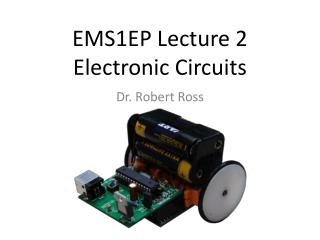
What’s next: buiding circuits We will use solderless breadboards to built some simple circuits (next week during the workshop):
Breadboard Solderlessbeadboards are the quickest tools for prototyping a new circuit.
!!! When you start to put components on your breadboard, avoid adding, removing, or changing components on a breadboard whenever the board is powered. You risk shocking yourself and damaging your components.
LEDs LEDs, or Light Emitting Diodes, are diodes that emit light when given the correct voltage. Like all diodes, they are polarized, meaning that they only operate when oriented correctly in the circuit. The anode of the LED connects to voltage, and the cathode connects to ground. The anode in the LEDs in this photo is the longer leg on each LED. LEDs come in many diferent packages.
Potentiometer - A resistor that can change its resistance. - Three connections. The outer leads are the ends of a fixed value resistor. The center lead connects to a wiper which slides along the fixed resistor. - The resistance between the center lead and either of the outside leads changes as the pot's knob is moved.
Resistor and switch button Resistor color coding scheme: http://www.create-california-online.net/Tutorials/Resistor_color_code_2/resistor_colorcode.htm
Voltage Regulator Voltage regulators take a range of DC voltage and convert it to a constant voltage. For example, this regulator, a 7805 regulator, takes a range of 8 - 15 volts DC input and converts it to a constant 5-volt output.
Summary • Introductions • Basic Electronics – review • Circuit components • Circuit relationships and rules • Building circuits