Download
1 / 21
210 likes | 374 Views
Integration of Photosynthetic Protein Molecular Complexes in Solid-State Electronic Devices. K.M. P. Bandaranayake and G. Hastings. Out lines. Solid State electronic devices (photodetectors, photovoltaic cells) Using Photosynthetic Protein molecular complexes

E N D
Integration of Photosynthetic Protein Molecular Complexes in Solid-State Electronic Devices K.M. P. Bandaranayake and G. Hastings
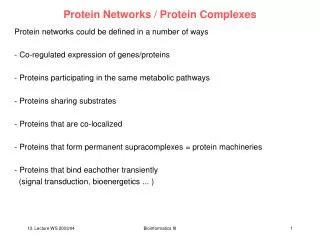
Out lines • Solid State electronic devices (photodetectors, photovoltaic cells) • Using Photosynthetic Protein molecular complexes • Why they use Photosynthetic Protein molecular complexes? • Fabrication of devices. • Orientation of proteins molecules, stability and internal Quantum efficiency
Why they use Photosynthetic Protein molecular complexes? • *Plants and photosynthetic bacteria contain protein-molecular complexes • that harvest photons with nearly optimum quantum yield and an expected • power conversion efficiency exceeding 20%. • Comparison with others • recombination losses • * Low cost
The photosynthesis complexes • Photosystem I (PSI) are isolated from spinach leaves. • Bacterial reaction centers (RC) are isolated from Rhodobacter (Rb.) Sphaeroides.
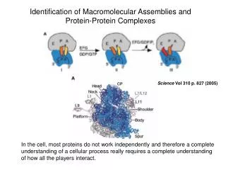
Thylakoid Membrane Major protein-cofactor complexes in the thylakoid membrane: Photosystem II Photosystem I Jon Nield, Imperial College, London
Reaction center (RC), purple bacterium Rhodobacter (Rb.) sphaeroides. (http://www.fuchs-research.net/images)
a bacteriochlorophyll dimer known as the special pair two monomer bacteriochlorophylls two bacteriopheophytins two quinones These molecules are symmetrically arranged in the L and M subunits, 2 but electron transfer is observed to occur principally through the L branch. (http://www.fuchs-research.net/images)
1.8 1.8 * P700 Electron transfer cofactors: P700 (Chlorophyll-a dimer) A0 (chlorophyll-a monomer) Qk (A1) (Phylloquinone) FX, FA and FB (Ion sulfur clusters) ~1 ps 1.6 1.6 P700 A + - - 0 1.4 1.4 30 ps Standard free energy (eV) 1.2 1.2 P700 F P700 A + + - - + + - - x x 1 1 ~20 ns 500 ns ~ ~ n n h h 200 ns P700 F + + - - B P700 F + + - - 1.0 1.0 500 ns ~ ~ A A P700 P700 0 0 Forward Electron Transfer Kinetics Brettel et al. Biochim. Biophys. Acta1507, 100-114 (2001)
Fabrication of (RC) devices 1 nm-thick layer of Cr to promote adhesion. Transparent ITO glass Gold thin, 4 nm-thick film of gold The substrate • 3,3’-Dithiobis (sulfosuccinimidylpropionate) • (Membrane crosslinker) • Nitriotriacetic acid • Finally, the NTA-functionalized surface is charged with 200 mM nickel sulfate
RC solution (0.2 mg/mL in 10 mM phosphate buffer pH 7.4, 0.05% LDAO and 0.02 M A6K/V6D (1:1)) for 1 h at 4 °C in the dark)
Fabrication of PSI devices The genetically modified protein (psaD-His) is immobilized on the Ni2+-NTA functionalized ITO/Au surface. Incubated with native PSI (in 50 mM Tris, 25 mM NaCl, 2 M sucrose, 0.02% Triton X-100, and 0.02 M A6K/V6D (1:1) for 1 h at 4 °C in the dark).
Tapping mode atomic force microscopy (TM-AFM) images of RC and PSI To confirm the orientation of the PSI and RC complexes we performed TM-AFM phase imaging in the intermittent contact mode and varied the potential between the AFM tip and the ITO/Au substrate. Tip V The sample to generate topographical images
Tapping mode atomic force microscopy (TM-AFM) images of RC and PSI • Note the phase changes in • the -1 V scan, relative to • the +1 V and 0 V scans. • The increase in phase in the • -1 V scan corresponds to an increase in the attractive forces • between the tip and the sample and indicates the presence of a positive charge trapped on the surface of PSI, mostly likely at the special pair, P700. • * The voltage dependence confirms that the rectifying PSI complexes are oriented with the P700 dimer face up.
(c)The phase profile of an assembled RC film showing a close-packed monolayer. * RCs are oriented with their electron-accepting special pair, P, facing the substrate.
Energy level diagram of a PSI photodetector. *To protect monolayer's of PSI assembled on functionalized ITO we deposit a thin coating of the archetype organic semiconductor tris(8-hydroxyquinoline) aluminum, Alq3. *Alq3 is also electron transporting material, thus under optical excitation at λ= 680 nm, charges are generated primarily in PSI; electrons are transferred to the ITO substrate, holes are trapped on the special pair, P700, and the device acts as a photodetector. *Fabrication of PSI-based devices is completed by deposition a 80-nm-thick film of Ag on ITO.
Energy level diagram of a RC photovoltaic cell *a 60 nm-thick protective layer of the preferentially electron transporting fullerene C60. C60 was chosen because of its relatively deep lowest unoccupied molecular orbital (LUMO) energy of 4.7 eV that could enhance electron transfer from the electron acceptor Qb in the RC. *After C60, a 12 nmthick layer of 2,9-dimethyl-4,7-diphenyl-1,10-phenanthroline (bathocuproine, or BCP) is deposited. Then deposited of an 80 nm thick Ag Cathode. *Damage to BCP facilitates electron extraction and the deep highest occupied molecular orbital (HOMO) of BCP effectively prevents the injection of holes into the device, markedly improving the device’s reversebias characteristics.
Frozen PSI solution *significantly degraded fluorescence The stability of PSI is assessed using its fluorescent spectrum (10K) Incubating PSI with A6K/V6D , dried (Blue shift) * Indicative of gradual structural changes in the light antennae of PSI. Incubating PSI without A6K/V6D (Inset) The stabilized PSI devices exhibit a photocurrent spectrum that matches the absorption spectrum, confirming solid-state integration of stabilized PSI, demonstrates that PSI has been successfully integrated in a solid-state environment.
The activity of an RC based device without A6K or V6D is confirmed by spectrally resolving the short circuit current using a Ti-sapphire CW laser tunable between λ = 790 nm and λ = 890 nm. Solid state device Wet electrochemical cell device The solution abs spectrum of RC *The photocurrent spectrum exhibits the characteristic peaks of both the solution absorption spectrum of the RC complexes, and a photocurrent spectrum of identical RC complexes in an electrochemical cell reproduced from ref 16. * In the inset, we show the effect of A6K/V6D stabilization on the current voltage characteristics of the devices. On average, the peptides were found to improve the open circuit voltage by a factor of 2-3.
*The short circuit current density of the RC-A6K/V6D devices is 0.12 mA/cm2 (an excitation int. of 10W/cm2 at λ= 808 nm.) *Under short-circuit conditions, a conservative estimate of the internal quantum efficiency of the device is 12%.
Conclusion *The photosynthetic complexes may be used as an interfacial material in photovoltaic devices. *Evolved within a thin membrane interface, photosynthetic complexes sustain large open circuit voltages of 1.1V without significant electron-hole recombination, and they may be self-assembled into an insulating membrane, further reducing recombination losses. *Peptide surfactants have proved essential in stabilizing these complexes during and after device fabrication. *Given typical quantum yields for photoinduced charge generation of > 95% it is expected that the power conversion efficiency of a peptide-stabilized solid-state photosynthetic device may approach or exceed 20%. *Similar integration techniques may applied to other biological or synthetic protein-molecular complexes.