Download
1 / 32
510 likes | 995 Views
Background and History of Fracture Control Plan for Fracture Critical Bridges. CE671 – Lecture 14. What is the AWS Fracture Control Plan?. Originally in The Guide Specifications for Fracture Critical Non-redundant Steel Bridge Members – Published by AASHTO - 1978

E N D
Background and History of Fracture Control Plan for Fracture Critical Bridges CE671 – Lecture 14
What is the AWS Fracture Control Plan? • Originally in The Guide Specifications for Fracture Critical Non-redundant Steel Bridge Members – • Published by AASHTO - 1978 • Presently contained in AWS D1.5 Chapter 12 • Moved into AWS in 1995 • AASHTO/AWS FCP for Non-redundant Members
What is the Fracture Control Plan? • Focuses on: • Material • Primary members, welds, consumables, weld repairs, etc. • Fabrication • Inspection of fabrication • Does not explicitly cover: • Design (Structural) • Drawings must identify FCM’s • In-situ inspection • In-situ maintenance
What are Fracture Critical Members (FCM’s)? • Defined by AASHTO LRFD • Component in tension whose failure is expected to result in the collapse of the bridge or the inability of the bridge to perform its function • Includes: • Primary members • Welds and consumables • Attachments (L>4”)
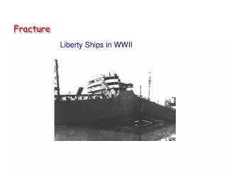
In The Beginning………Prior to 1970 • No Toughness requirements for bridge steels or weldments • A588 steel Charpy for information only • No toughness requirement for welds (except electroslag) • No qualification testing • No required field inspections • No certified weld inspectors or ASNT certified inspectors • Stress range fatigue requirements just developed • Non-weldable steels (A440) available
Point Pleasant Bridge Collapse • Eye bar chain suspension bridge • Designed as cable suspension bridge • Built in 1929 collapsed 1967
Eye Bars Total Bridge Collapse • Bridge reassembled on land to determine cause of fracture • Note eye bar chain • One lane of bridge backed up at time of collapse
Eyebars • Pin connected • Two bars per chain • Thickness varied along bridge • Heat treated 1060 steel • High Carbon (0.60%) • Low Toughness • Relatively high strength
Ductile Failure Brittle Fracture Failure Events • Brittle facture of one side of eye • Remaining ligament under axial + bending due to eccentricity • Ductile failure of ligament causing force transfer to intact eyebar • Eccentricity of force from one eyebar on joint causes joint to rotate and unfractured eyebar pulls off of pin
Fractured Eye Bar • Left Side ductile fracture • paint spalling due to large plastic strain • almost full section plastified • Right side no ductility • low toughness brittle fracture
Fracture Surface Origin No Evidence of Ductility
Cleaned Fracture Surface 0.15 in. • Fracture initiated from semicircular cracks at pin hole of eyebar • Two small cracks • growth mechanism most likely stress corrosion • fatigue stresses extremely low in eyebar chain • cracks slowly grew during the approximately 40 year service life
Conclusions and Dilemma • Collapse Caused by Unstable Crack Propagation in One Eye Bar • Small Semicircular Cracks at Pin Hole Initiated the Fracture • What to Do About the St. Mary's Bridge? • Identical Bridge • About the Same Age • Same Material • More Traffic
Solution • Inspect eyebars on St. Mary's Bridge • Ultrasonic inspection from edge of bar • difficult access in winter with ice on eyebars • inspectors quit due fear of falling • unable to differentiate between corrosion pits on pin hole and shallow cracks • Result: bridge taken out of service and torn down
Crack Length-a Stable Growth acritical adetectable Remaining Life ainitial Life Inspection
Toughness & Inspection • adetectable must be less than acritical • if not safety of structure cannot be reliably determined • St. Mary's Bridge • adetectable greater than acritical therefore inspection could not reliably determine the safety of the bridge from brittle fracture • Minimum remaining life after an inspection dependent upon the difference between acritical and adetectable • larger the difference the greater the remaining life and larger the inspection interval for a given stress range
Steel Toughness and Inspection • Fracture Toughness of Steel Determines Maximum Stable Crack Size- acritical • Tolerable Flaw Size Increases as Toughness Increases • Maximum Flaw Size You Can Find for a Given Reliability, adetectable, Must Exceed acritical • Reliability Must be Based Upon Field Conditions Not Laboratory Conditions • Height Hazards, Weather, and Lighting Influence Field Performance
Outcome • Material Toughness Specifications • Bridge Inspections
Initial Material Requirements • Charpy V Notch (CVN) Specimen • Cheap Compared to Drop Tear Test or Fracture Mechanics Specimens • Correlations Between CVN and Fracture Mechanics Specimen Developed for Nuclear Reactor Surveillance Specimens • Dynamic Toughness Converted to Intermediate Loading Rate Using Temperature Shift (Crack initiation control not crack propagation) • Initial Proposal Present Zone 2 Requirements • Texas-Zone 1 • Alaska-Zone 3
Twin Girder Bridge (less than 1 year old)
Full Depth Girder Fracture Continued to Carry Traffic!
Semi-Circular Crack in Weld Repair Crack Driving Force From Residual Stress From Web to Flange Weld Electroslag Flange Butt Weld Lack of Fusion Defect At Location of Welding Wire Spool Change Full Thickness Weld Repair
Location of Silver Dollar Sized Initial Crack in Repair Weld
acr1 Change Due to Lower Toughness acr2 < acr1 Loss of Life Due to Larger ai ai Larger ai Cycles or Time to Failure Influence of Initial Flaw Size
Outcome • Increased Emphasis on Weld Repair • Require Qualification of Weld Repair Procedure • Electroslag Welding Outlawed for Tension Members • Required Both UT and RT on Critical Welds
Specification Trade Offs Crack Size acritical Increase in Life Through More Stringent Inspection Structures Life (N)
Specification Trade Offs Crack Size Increase in Life From Decrease in Stress Range acritical 10% reduction in Stress Range Produces 37% in Life Structures Life (N)
Specification Trade Offs Increasing Toughness Crack Size Larger acritical acritical Increase in Life From an Increase in Toughness Structures Life (N)
Fracture Critical Members Specification • Increase Reliability by: • Reduced Design Stress Ranges (Decrease Crack Growth) • Higher Toughness (Increase Crack Tolerance for Inspectability) • RT and UT Shop Inspection (Increase Inspection Reliability) • Weld Qualification Tests Including Repair Welds (Tighter Control of Weld Quality ?)
Fracture Critical Members Specification • Increase Reliability by: • More Frequent and In-depth Inspections