Download
1 / 56
570 likes | 762 Views
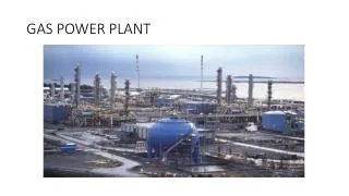
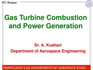
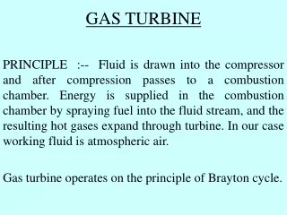
Basics in the Thermodynamic Analyses of the Gas Turbine Power Plant. Prof. R. Shanthini Dept. of C & P Engineering University of Peradeniya Sri Lanka. fuel. hot gases. Combustion chamber. compressed air. Comp- ressor. Gas turbine. Compressor shaft. Turbine shaft.

E N D
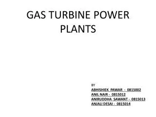
Basics in the Thermodynamic Analyses of the Gas Turbine Power Plant Prof. R. Shanthini Dept. of C&P Engineering University of Peradeniya Sri Lanka
fuel hot gases Combustion chamber compressed air Comp- ressor Gas turbine Compressor shaft Turbine shaft Gen gases to the stack atmospheric air Gen stands for Electricity Generator
(WGT) out W stands for work flow rate and GT stands for Gas Turbine fuel hot gases Combustion chamber compressed air Comp- ressor Gas turbine Gen gases to the stack atmospheric air
(QCC) in (WGT) out Q stands for heat flow rate and CC stands for Combustion Chamber hot gases Combustion chamber compressed air Comp- ressor Gas turbine Gen gases to the stack atmospheric air
(QCC) in (WGT) out (WC) in W stands for work flow rate and C stands for Compressor hot gases Combustion chamber compressed air 3 2 Comp- ressor Gas turbine Gen 4 1 gases to the stack atmospheric air
(QCC) in (WGT) out (WC) in hot gases Combustion chamber compressed air 3 2 Comp- ressor Gas turbine Gen 4 1 gases to the stack atmospheric air
(QGT) out (WGT) out + m g ( Z – Z ) g r 3 4 = m ( h – h ) 3 4 g 2 2 + m ( C – C ) / 2 3 4 g Steady flow energy equation applied to the flow across turbine: hot gases 3 + Gas turbine m stands for mass flow rate of gas, hstands for enthalpy, C stands for speed of gas flow gstands for gravitational acceleration, & Z stands for height above reference level 4 g gases to the stack r
(QGT) out (WGT) out - (QGT) + m g ( Z – Z ) out g r 3 4 = m ( h – h ) 3 4 g 2 2 + m ( C – C ) / 2 3 4 g hot gases = + 3 + Gas turbine Assumptions: - Adiabatic condition prevails across the gas turbine 4 gases to the stack - Kinetic energy changes are negligible compared to enthalpy changes - Potential energy changes are ignored
(WGT) out = m ( h – h ) 3 4 g hot gases = 3 + Gas turbine Assumptions: - Adiabatic condition prevails across the gas turbine 4 gases to the stack - Kinetic energy changes are negligible compared to enthalpy changes - Potential energy changes are ignored
m ( h – h ) 3 4 g (WGT) out hot gases = 3 Gas turbine Assumptions: - Adiabatic condition prevails across the gas turbine 4 gases to the stack - Kinetic energy changes are negligible compared to enthalpy changes - Potential energy changes are ignored
m ( h – h ) 3 4 g (WGT) (WGT) out out = m C ( T – T ) g pg 3 4 hot gases = 3 Gas turbine Assumption: - Gases flowing through the turbine behave as ideal gases 4 gases to the stack
m ( h – h ) T 3 4 3 g (WGT) out T 4 = m C ( T – T ) g pg 3 4 = 3 Gas turbine Temperature at the outlet Temperature at the inlet 4 Specific heat of gas at constant pressure Mass flow rate of gas
T = m C ( T – T ) 3 g pg 3 4 (WGT) out T 4 3 = changes Gas turbine fixed fixed = ? 4 free to choose, but we fix it at some value
= T T P P P 4 3 = m C ( T – T ) 4 3 3 g pg 3 4 (WGT) out T at the given and 4 P = 4 3 = To get maximum work output from the turbine, Gas turbine (P stands for pressure) = ? should be as small as possible How small should T4 be ? 4
T = m C ( T – T ) 3 P g pg 3 4 3 (WGT) out T 4 P 4 3 3 Gas turbine real flow P3 T ideal flow 4 4s P4 4 Specific Entropy (s)
P P T = m C ( T – T ) 3 4 3 g pg 3 4 (WGT) ) (-1)/ ( out P 4 = T T 3 4s P 3 T 4s (WGT) out,ideal = m C ( T – T ) g pg 3 4s 3 For the ideal flow (ideal gas at constant specific entropy): Gas turbine where is the isentropic constant 4 Therefore,
T (WGT) m C ( T – T ) out g pg 3 4 = = m C ( T – T ) (WGT) g pg 3 4s out,ideal - T T 4 3 = - T T 4s 3 Turbine Efficiency 3 Gas turbine 4
T T T (-1)/ ( ) P = 4 T T ) T T ( T T 3 = – – 4s P 4s 3 3 3 4 = (WGT) out = m C ( T – T ) (WGT) g pg 3 4s out,ideal Governing equations: 3 Gas turbine 4
T (WGT) out = 350 kg/s = 1.1 kJ/kg.s m g = 1200 K = 1.3 = 1 bar C pg = 88% P T γ T 4 4 3 Let‘s do some Excel sheet calculations across the turbine 3 Data: Determine Gas turbine 4 for P3 varying in the range of 2 to 15 bar
= 88% T Turbine outlet temperature increases with decreasing turbine efficiency
= 88% T Turbine work output decreases with decreasing turbine efficiency
(WGT) out fuel hot gases Combustion chamber compressed air Gas turbine Comp- ressor Gen gases to the stack atmospheric air
(QCC) in (WGT) out (WC) in hot gases Combustion chamber compressed air 3 2 Gas turbine Comp- ressor Gen 4 1 gases to the stack atmospheric air
(QCC) in (WGT) out (WC) in hot gases Combustion chamber compressed air 3 2 Gas turbine Comp- ressor Gen 4 1 gases to the stack atmospheric air
+ m g ( Z – Z ) a r 3 4 (QC) + m ( h – h ) 2 1 a out 2 2 + m ( C – C ) / 2 2 1 a Steady flow energy equation applied to the flow across compressor: compressed air 2 Subscript astands for air Comp- ressor (WC) = in 1 atmospheric air
+ m g ( Z – Z ) a r 3 4 (QC) + m ( h – h ) 2 1 a out 2 2 + m ( C – C ) / 2 2 1 a Assumptions: - Adiabatic condition prevails across the compressor compressed air - Kinetic energy changes are negligible compared to enthalpy changes 2 - Potential energy changes are ignored Comp- ressor (WC) = in 1 atmospheric air
+ m ( h – h ) 2 1 a Assumptions: - Adiabatic condition prevails across the compressor compressed air - Kinetic energy changes are negligible compared to enthalpy changes 2 - Potential energy changes are ignored Comp- ressor (WC) = in 1 atmospheric air
m ( h – h ) 2 1 a = m C ( T – T ) a pa 2 1 Assumption: - Air flowing through the compressor behaves as an ideal gas compressed air 2 Comp- ressor (WC) = in 1 atmospheric air
T = m C ( T – T ) (WC) 2 a pa 2 1 in T 1 2 Comp- ressor T at the inlet 1 T at the outlet Specific heat of air at constant pressure Mass flow rate of air
T = m C ( T – T ) (WC) 2 a pa 2 1 in T 1 = ? 2 Comp- ressor fixed 1 changes = fixed free to choose, but we fix it at some value
= T T ; P P P = m C ( T – T ) 1 2 (WC) 2 2 2 a pa 2 1 in T at the given and 1 = P 1 = ? 2 Comp- ressor To give minimum work input to the compressor, 1 = should be as small as possible How small should T2 be ?
P T 2 = m C ( T – T ) (WC) 2 a pa 2 1 in T 1 P 1 2 3 Comp- ressor T P3=P2 2 4 2s real flow 4s P4=P1 1 ideal flow 1 Specific Entropy (s)
= ? P T = m C ( T – T ) (WC) 2s 2 a pa 2 1 in ) (-1)/ ( P 2 = T T 1 2s P 1 T 1 (WC) P in,ideal 1 = m C ( T – T ) a pa 2s 1 = For the ideal flow (ideal gas at constant specific entropy): 2 Comp- ressor 1 Therefore, = =
(WC) in,ideal = C (WC) in = m C ( T – T ) a pa 2s 1 - T T 1 2s = - m C ( T – T ) T T a pa 2 1 1 2 Compressor efficiency 2 Comp- ressor 1
C (-1)/ ( ) P = 2 T T / – ) T T ( T T 1 = + 2s P 2s 1 1 2 1 / (WC) = (WC) in C in,ideal / m C ( T – T ) = C a pa 2s 1 Governing equations: 2 Comp- ressor 1
2 Comp- ressor C = 350 kg/s = 1.005 kJ/kg.s 1 m a = 300 K = 1 bar = 1.4 (WC) C in pa = 85% T P T γ 1 1 2 Let‘s do some Excel sheet calculations across the compressor Data: Determine for P2 varying in the range of 2 to 15 bar
= 85% C Compressor outlet temperature increases with decreasing compressor efficiency
= 85% C Work input to the compressor increases with decreasing compressor efficiency
(WGT) out (WC) in W net fuel hot gases Combustion chamber compressed air Comp- ressor Gas turbine Gen gases to the stack atmospheric air
(WC) - in,ideal W = net (WC) in W (WGT) net,ideal out (WGT) - out,ideal = Net work output from the turbine is the power available for electricity generation Net work output under ideal conditions is the maximum power available for electricity generation
and = 85% C = 88% T
and = 85% C = 88% T
(QCC) in W net hot gases Combustion chamber compressed air 3 2 Comp- ressor Gas turbine Gen 4 1 gases to the stack atmospheric air
(QCC) in W net hot gases Combustion chamber compressed air 3 2 Comp- ressor Gas turbine Gen 4 1 gases to the stack atmospheric air
fuel hot gases Combustion chamber compressed air 3 2 (QCC) in,ideal = m ( h – h ) 3 2 a Assumptions: - Kinetic energy changes are negligible - Potential energy changes are ignored - Fuel flow rate is negligible compared to the air flow rate
fuel hot gases Combustion chamber compressed air 3 2 (QCC) in,ideal = m ( h – h ) 3 2 a = m C ( T – T ) a pa 3 2 Assumption: - Air flowing through the compressor behaves as an ideal gas
fuel hot gases Combustion chamber compressed air 3 2 CC CC CC (QCC) (QCC) in in,ideal = m C ( T – T ) a pa 3 2 / = / is the compressor efficiency
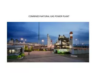
fuel hot gases Combustion chamber compressed air 3 2 CC = 350 kg/s (QCC) in = 1.005 kJ/kg.s m a C pa = 80% P P 2 3 = Let‘s do some Excel sheet calculations across the combustion chamber Determine
= 80% CC = 80% CC
(QCC) (QCC) in in hot gases Combustion chamber compressed air 3 2 Comp- ressor Gas turbine Gen 4 W W 1 th net net gases to the stack atmospheric air Thermal efficiency =