Download
1 / 18
190 likes | 532 Views
Survivable Computing Environment to Support Distributed Autonomic Automation. Dr. Andrés Lebaudy, Mr. Brian Callahan, CDR Joseph B. Famme USN (ret) ASNE Controls Symposium Biloxi, MS December 10-11, 2007. 1. Damage Control Requirements.

E N D
Survivable Computing Environment to Support Distributed Autonomic Automation Dr. Andrés Lebaudy, Mr. Brian Callahan, CDR Joseph B. Famme USN (ret) ASNE Controls Symposium Biloxi, MS December 10-11, 2007 1
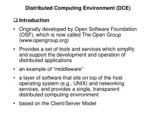
Damage Control Requirements Naval studies show thatships are seldom lost to primary damage (direct blast effects) but the result of secondary damage: the progressive spreading of fire and flooding into surrounding areas Key Challenge is to Increase Control System Survivability & Decrease Casualty Response Time Past experience has demonstrated that when engineering casualties or damage occurs a human is too slow and vulnerable, and requires enormous logistical and medical support Distributed, Survivable Autonomic Processing Contributes to Reduced Response Time 2
ONR Multi-level Control Integration Mission Control Layer Situational Awareness Operator Interfaces System Coordination Layer Situational Awareness Decision Aids ---- Systems Interactions Autonomous System Layer Survivability HM & DC Signatures Electrical WAN WAN Engineering Propulsion Defining the Requirements for Survivable Computing 4
What is a Smart Valve? Smart Valves sense or infer valve and fluid parameters valve (actuator) position fluid flow rate upstream and downstream fluid pressure fluid temperature* Embedded, programmable microprocessor-based controller controls valve actuator filters sensor data estimates flow rate perform valve actuator diagnostics can be programmed to be “intelligent” Communication interface interface with device- or field-level network send/receive information to/from other devices on the network send/receive information and commands to/from next highest control system tier Courtesy of Tyco International Ltd.
Smart Valve Applications Method 1: Hydraulic Resistance Method 2: Flow Inventory • Requires only pre-hit communication • Each valve independently determines whether it lies along the rupture path • Valves initiate a closure sequence after pre-configured time delay • Activates only when pressure and flow conditions are abnormal • Requires full or partial communication between adjacent smart valves • Neighboring smart valves calculate flow balance • Rupture detected when flow into the zone is not equal to flow out of the zone • Valves operate to isolate zone • Allows for estimating rupture or leak size • Number of branches and uncertainties in individual flow estimates determines “size” of rupture that can be reliably detected
Live Fire Test of “SmartValve” Technology & Autonomic Fire Suppression System • AFSS EDM successfully responded to all of the live-fire test scenarios (Shadwell 2002) • Follow-up testing of an AFSS prototype was demonstrated successfully during a Weapons Effects Test (WET) on ex-USS Peterson (Peterson 2003). 8
PAC Component Modular Design • Multi-domain functionality-including logic, motion, and process control-on a single very flexible and highly configurable platform. • Mil Qualified Shock, Moisture … 9
Multi-level Mil-spec Control Modules • Computational and storage resources that grow with application demands • Resistant to component failures by distributing the processing load 10
Next Generation Control Software • Survivable, reconfigurable third-generation graphical design tool • Windows-based software package that relies on intuitive drag-and-drop, undo-redo, and cut-copy-paste functionality 11
Next Generation Graphical Design Environment • Comprehensive set of field-proven function blocks • state-diagramming features allow design engineers to define operational states 12
Field-proven function blocks Examples: • Controller Blocks (e.g., PID controller, lead-lag controller) • Signal Conditioning Functions (e.g., characterizer, rate limiter, track & hold) • Signal Comparator Blocks (e.g., high/low alarm, equality, thresholding) • Mathematical Operators (e.g., addition, natural log, exponent, sine) • Logic Functions (e.g., NAND gate, XOR gate, RS flip flop) • General Purpose Operators (e.g., timer, ramp profile, multiplexer, A/B switch) • Hardware Access (e.g., analog input, barograph display, pushbutton) • Networking Operators (e.g., broadcast, receiver, parameter synchronization) • Diagnostic Operators (e.g., data recorder, hardware status monitor) • Text Manipulation (e.g. string constants, concatenation, left, right, etc.) 13
Fleet Modernization INSTALLATION EXAMPLES Naval Surface Warfare Center (NSWC) in Philadelphia to accomplish Ship Alteration 480D for the following ships: USS Boone, USS McInerny (FFG 8), USS Gary (FFG 51), and USS Vandergrift (FFG 48). To regulate the cooling of the four SSDGs, as well as the SSDG waste heat temperature, the fuel temperature in two sets of oil service and transfer heaters, the hot water tank temperature, and the start-air-mixer air temperature. The PACs also control the main engine lube oil purifier, cooler, and service pressure loops. 14
Distributed I/O Processing Saves Cable Cost Chameleon PAC Can Interface With Any Control System Machinery Control System HMI & Processors • Enclosureless Mini-RTU/DAU • Highly distributed, located in close proximity to machinery - Reduced Cable Cost • Wired or secure wireless communications • Topologies supported: Ring, Bus, Star, Mesh • Interface to smart sensors 1451.4 and 1451.5 • DDS Publish / Subscribe • Industrial Communications • Network Gateways • Legacy I/O TSCE Network e r u c e S k n L i E C S T 1451.4 1451.4 PWM RTD 4-20mA SecureBluetooth or 802.11 a/b/g Pressure 1451.4 RPM 1451.5 / LonTalk Temperature ZigBee Vibration Copper/Fiber10/100MBps Ethernet Ring with DDS Communications ProfiBUS Ethernet/IP 0-5V 4-20mA e r u c e g S / b / a 1 RTD 1 . 2 0 8 TSCE Network
Compare Conventional Wiring to Distributed Process Wiring TSCE Conventional Compartment I/O Drop Distributed Compartment I/O Drop Distributed Compartment I/O Drop • Distributed • Savings: • Installation Costs • Weight Ethernet etc. MIL-SPEC RTUs Machinery Machinery
CONCLUSIONS New Shp Classes will be able to employ Decentralized Ship System Architectures with Distribute Control Systems in order to Improve Rapid System Recovery / Ship Survivability and Fight Through Capability Survivability is Achieved through Computational and Process Electronics Protection Provided by Hardware, Hardware Architectures / Control Software that is Mil-Spec and Locally Reconfigurable Using Control Hardware that has been Tested to Highest Level of Survivability to Reduce Vulnerability to Damage and Ensure No Critical Single Points of Vital System Failure This solution Supports Reduced Crew Size, Lowers the Weight of Wire, and the Cost to Install Control Systems thus Improving Ship Production. Proposed solutions are Technical Readiness Levels 7, 8 & 9. 18