Download
1 / 26
260 likes | 388 Views
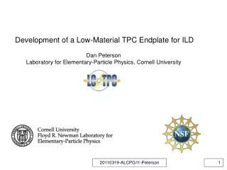
Development of a Low-Material TPC Endplate for ILD Dan Peterson Laboratory for Elementary-Particle Physics, Cornell University. Work at Cornell: development of the endplate and module mechanical structure to satisfy the material and rigidity requirements of the ILD.

E N D
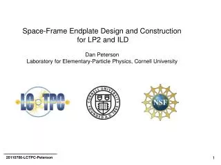
Development of a Low-Material TPC Endplate for ILD Dan Peterson Laboratory for Elementary-Particle Physics, Cornell University LCWS 2012 Arlington D. Peterson
Work at Cornell: development of the endplate and module mechanical structure to satisfy the material and rigidity requirements of the ILD. The ILD TPC has dimensions: outer radius 1808 mm inner radius 329 mm half length 2350 mm →Prototype tests during development of the ILD TPC endplate design → ILD TPC endplate design, analysis →LP2 endplate construction and testing as a validation of the ILD design →Further measurements on the LP2 endplate →Further analysis on the ILD endplate design →Comments on viability of constructing the ILD endplate LCWS 2012 Arlington D. Peterson
Competing Requirements for the ILD TPC endplate Detector module design: Endplate must be designed to implement Micro Pattern Gas Detector (MPGD) readout modules. Modules must provide near-full coverage of the endplate. Modules must be replaceable without removing the endplate. Low material – Limit is set by ILD endcap calorimetry and PFA. 25% X0 including readout plane, front-end-electronics, gate 5% cooling 2% (6% ?) power cables 10% (6% ?) mechanical structure (this talk) 8% Rigid - limit is set to facilitate de-coupled alignment of magnetic field and module positions. Precision and stability of x,y positions < 50μm ( see LC Notes LC-DET-2012-072 ) Thin - ILD will give us 100mm of longitudinal space between the gas volume and the endcap calorimeter. 2012-10-22 LCWS 2012 Arlington D. Peterson 3
In 2008, Cornell constructed two endplates for the LCTPC Large Prototype (LP1). These were shipped August 2008 and February 2010, and are currently in use. Inside the chamber Outside the chamber The endplate construction was developed to provide the precision required for ILD; precision features are accurate to ~30 μm. The accuracy was achieved with a 5-step process, with 3 machining steps and 2 stress relief (cold shock) steps. For the LP1 endplate, did not have a goal to meet the material limit; the bare endplate has mass 18.87 kg over an area of 4657 cm2, (mass/area) / (aluminum radiation length (24.0 g/cm2) ) = 16.9% X0, 2x goal. back-frames, after liquid N2 immersion 2012-10-22 LCWS 2012 Arlington D. Peterson 4
LP1 endplate, thick aluminum lightened, all aluminum space frame aluminum/ carbon fiber hybrid Various technologies were considered for the ILD endplate ( illustrated here for an LP1-size endplate ). The LP1 endplate structure is rejected because of high material. Various lighted endplates illustrated contributions to the endplate strength. Low material hybrid construction was considered in an effort to provide the strength of the LP1 design, with significantly reduced material. But, there is insufficient rigidity when scaled to the size of the ILD. Only a space-frame promises to provide the required strength-to-material. 2012-10-22 LCWS 2012 Arlington D. Peterson 5
The ILD endplate design is a space-frame and shown here as the solid model used for the Finite-Element-Analysis (FEA). (inside view) This model has full thickness 100mm, outer radius 1.8m, 99500 cm2 mass 136 kg, material thickness ( frame only) 1.37g/cm2, 5.7% X0. Aluminum: X0=8.9cm ρ=2.7 g/cm3 , X0=24.0 g/cm2 . 2012-10-22 LCWS 2012 Arlington D. Peterson 6
Module Back-frames 240 modules in this design 37700 mm2 per module Individual module back-frames contribute significant material. which is counted as part of the 8% X0 goal. The current (lightened) module back-frames have mass 290g. With 240 modules, the total mass is 69.6kg or 2.9% X0. Thus the total material is 8.6%; the 8% goal is not met. Module back-frames can be produced in carbon fiber to meet the goal. (inside view) 2012-10-22 LCWS 2012 Arlington D. Peterson 7
space-frame designs The ILD endplate solid model(previous slides 7 & 8) is modeled in the “equivalent-plate” space-frame design; the separating members are thin plates. The “strut” space frame design is an alternative. The thin plate thickness and width are adjusted to achieve rigidity and material equivalent to a strut design. The ILD was modeled with equivalent plates only because the struts were too complicated for the FEA. The final implementation of the ILD endplate may be either the strut or thin plate designs. A construction design will be discussed. 2012-10-22 LCWS 2012 Arlington D. Peterson 8
FEA calculations of deflection and stress (stress is not shown) Endplate deflections were calculated with finite element analysis (FEA). Endplate Support: outer and inner field cages Maximum deflection of the model: 0.00867 mm/100N Calibration: 100N is the force on LP1 due to 2.1 millibar overpressure ratio of areas: (area of ILD)/(area of LP1) =21.9 ILD TPC endplate deflection for 2.1 millibar overpressure (2190N) = 0.19 mm ( Without the space-frame structure, the simple endplate deflects by 50mm. ) The maximum stress is 9.2 MPa while the yield limit is 241 MPa. Validation of the FEA for a complicated structure will be discussed. deflection is changed slightly in a new release of the FEA 2012-10-22 LCWS 2012 Arlington D. Peterson 9
Validation of the FEA The ILD endplate design study involves endplates at 3 levels of scale. The LP1 and LP2 endplates represent small sub-sections of an ILD endplate. Small test beams represent a slice through the LP1 or LP2 endplates. The measured performance, compared to FEA calculations, of the small test beams and LP1 and LP2 endplates, provide validation of calculations for the ILD endplate. 2012-10-22 LCWS 2012 Arlington D. Peterson 10
100 mm Validation of the FEA with small test beams Small test beams represent sections across the diameter of the LP1/LP2 endplate. For each small test beam, there is a solid model that was used for the FEA. Deflection of the physical prototypes was compared to the FEA. 2008, LP1 Al-C Hybrid strut space-frame plate space-frame (carbon fiber) (Carbon fiber material is specified to have the same rigidity as the aluminum and is treated as aluminum in the FEA. Deflection measurements of the physical prototypes agree with the FEA. (presented earlier) 2012-10-22 LCWS 2012 Arlington D. Peterson 11
Validation of the FEA with 0.8 meter diameter, LP1 size, endplates date: 20100330 date: 20121019 Space-frame endplates of the size of the LC-TPC LP1 TPC were modeled in both “strut” and “equivalent plate” designs. Deflection of the two models agree by design; maximum deflection is 23 microns for 100N load at the center module. 2012-10-22 LCWS 2012 Arlington D. Peterson 12
LP2 endplates The first of two LP2 space-frame endplates was completed 25-March-2012. This is a fully functional replacement for LP1endplate, shown with the lightened module back-frames. One will be sent to DESY, where we can study system operation. Another will be kept for measurements of long term stability and lateral strength/accuracy. LCWS 2012 Arlington D. Peterson
Constructed LP2 endplate is a “strut” space-frame. 132 struts, 5 minutes to install, ~11 hours Initial alignment: inside surface held flat (clamps) outer plate adjusted to be flat (25 μm) initial adjustment of struts is easier than anticipated. fine and coarse thread screws, 10-32, 10-24, metric equiv: 4.88-0.794 4.88-1.058 difference: 96 turns/inch, 0.264mm/turn alignment iteration: ~ 2 hours All of the math is in the strut mounts. An issue: there are difficulties installing the mounting brackets. Some minor modifications will make this easier. LCWS 2012 Arlington D. Peterson
Validation of the FEA with 0.8 meter diameter LP2 endplate The FEA predicts a longitudinal deflection of 23 microns / 100 N load. (with the load applied at the center module.) Measured deflection is 27 microns/100 N load, 17% higher. measuring the deflection Load, Newtons LCWS 2012 Arlington D. Peterson
Comparison of deflection for LP1/LP2 endplates: FEA vs. measurements calculated measured mass material deflection stress deflection kg %X0 μm MPa μm (100 N) (yield: 241) (100 N) LP1 18.87 16.9 29 1.5 33 LP2 Space-Frame 8.38 7.5 23 4.2 27 (strut or equivalent plate) Lightened 8.93 8.0 68 3.2 Al-C hybrid Al 7.35 7.2 (68-168) (3.2-4.8) (channeled plus fiber) C 1.29 Channeled Al 7.35 6.5 168 4.8 The original LP1 endplate was compared to the FEA earlier. In both LP1 and LP2, the measured deflection is about 15% higher than from the FEA, which is close for the level of detail of the model. LCWS 2012 Arlington D. Peterson
Inside surface flatness Note: in the original alignment, the inside surface is held on a flat surface, the outer disk was aligned to the specified height. Total run-out of the inside surface: (6 months later) 0.0109 inch; 277 microns Alignment procedure may not produce a flat inner surface. Or, the distortion may have occurred after aging. My guess: built-up out-of-tolerances of the components and compensating unequal stresses in the struts resulted in the observed distortions. (This can be measured in second endplate.) 2012-10-22 LCWS 2012 Arlington D. Peterson 17
Inside surface flatness … corrected The strut design allows alignment correction. After 1 iteration of re-alignment: Total run-out: 0.0070 inch; 178 microns About 8 struts must be adjusted for a each of two local deformations. Demonstrates the ability to adjust the struts to correct flatness of the endplate surface. 2012-10-22 LCWS 2012 Arlington D. Peterson 18
LP2 endplate Major parts: manufactured with 5-step iterative machining and stress relief. achieved required tolerance of precision surfaces Assembly: 132 struts, 5 minutes to install, ~11 hours Initial alignment: ~2 hours/iteration, ~3 iterations re-alignment of “inside-the-chamber” surface, measure and adjust, ~ 2 hours/iteration, adjusting ~8 struts at a time, demonstrated ability to achieve ±100 μm accuracy Rigidity: 27 μm / 100 N center load. ILD endplate The FEA result, 0.19mm deflection with 2.1 millibar overpressure, is validated with LP2 measurements. Maybe reality is 17% greater. FEA of the “equivalent plate” model can be used for other tests: - thickness variations - error propagation of out-of-tolerance modules - deformation due to discrete support points - fewer layers (larger modules) 2012-10-22 LCWS 2012 Arlington D. Peterson 19
Further analysis of the ILD design: effect of increasing the endplate thickness rigidity vs thickness earlier version of FEA It was initially expected that the strength could be improved by asking ILD for more longitudinal space. However, the improvement with thickness diminishes (deviates from power law) above 100mm. The deflection decreases from 220 microns to 160 microns with a 200mm total thickness. The cause for the deviation from a power law is small buckling, ( most visible in inner layer) . Thus, the same improvement in deflection can be found with a modest increase in the back-disk thickness. 2012-10-22 LCWS 2012 Arlington D. Peterson 20
Further analysis of the ILD design: effect of installing an out-of-tolerance module Add a stress which is equivalent to ~ 0.02 mm total strain, across diagonal. This acts like a module with misaligned locating holes. (Assuming that there are no other modules to lock the endplate alignment) the effect travels a long distance through the endplate. At a distance of 5 modules, module displacement is ~50% of the applied strain. The inner ring can be seen to rotate on the order of 10% of applied strain. A tolerance of ~0.030 mm is required for locating holes on the endplate and modules to avoid propagating misalignment into the endplate, while defining the location of the modules on the endplate. stress vertical motion 2012-10-22 LCWS 2012 Arlington D. Peterson 21
Further analysis of the ILD design: chamber support points vertical Endplate is supported at 4 points (red arrows) upper points are constraints, right fixed, left sliding lower points are forces Endplate load at center, 4 points, 400 N total (blue arrows) Longitudinal position at outer o-ring is fixed (by the field cage). Total vertical motion, center w.r.t mount, is 0.017mm/400N If the total load per endplate is 1000kg, or 10,000N, total vertical motion is 0.43mm . However, the motion is smooth over the distance; the motion over a module is ~50μm . This is at the threshold of loading the modules. horizontal longitudinal 2012-10-22 LCWS 2012 Arlington D. Peterson 22
Further analysis of the ILD design: effect of changing the number of module rows We can consider an endplate with larger modules. The baseline design has 8 rows of modules, 37700 mm2 per module. With 4mm2 per pad, there are ~10000 pads/module. The 4-row design has 145000 mm2 per module. Longitudinal displacement increases by a factor of 1.4 Z motion is shown. 2012-10-22 LCWS 2012 Arlington D. Peterson 23
In the 4-row design, local distortions of 44 microns (0.002mm/100 N) can be seen in the back-disk. These are not seen in the 8-row design. However, this distortion is not in the main plate, which locates the modules. And, this is not the maximum stress point. Maximum stress is in the inner layer radial sections and also increases by a factor of 1.4 . Stress is not close to yield. The distortion is probably greatly reduced with a slightly thicker back-disk. x motion is shown 2012-10-22 LCWS 2012 Arlington D. Peterson 24
Issues related to the use of struts vs. plates. On slide 9, stated that the ILD can be implemented with struts of equivalent plates. Plates can be made with precision height; adjustment is not necessary (or possible) Plates must be glued in place. I have chosen the strut design for the LP2 endplate because it does not require development of a procedure for gluing the 2-dimesional array. A procedure can be developed for gluing after placement of the plates. It will require semi-automatic glue injectors which would be cost effective for the ILD scale. Struts are adjustable at a very fine scale. Adjustment is easier than expected. A full iteration, height measurements and adjustment, is about 2 hours on LP2. A re-alignment operation corrects the distortion of the inner surface. Struts require attachment of the mounts with aluminum screws (3.35mm), which must be tightened to ~40% of the yield strength. Creep may be a problem. One of the designs may have an advantage in the required mass in the mounting. 2012-10-22 LCWS 2012 Arlington D. Peterson 25
Issues for the construction of the ILD endplate Machining: we are looking at a 12 foot travel milling machine. They exist, but global tolerance is ~125 microns Handling: inner and outer plates will require fixtures for handling and shipping Stress relief: requires a 12 foot diameter tub of liquid nitrogen (solvable). Assembly alignment: I use a ground plate as an assembly jig. Does not scale to ILD. Solvable, set up stands with optical levels. Assembly: ~3000 struts, 5 minutes each, 250 hours Endplate alignment: not a 3000 degree of freedom exercise only ~5-8 struts must be changed at any one time. ILD assembly: endplate may require temporary stiffening supports LCWS 2012 Arlington D. Peterson