Download
1 / 25
250 likes | 445 Views
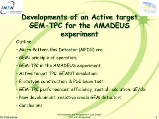
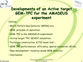
Prototype Development of a GEM-TPC for the SuperFRS. OUTLINE. Introduction and Motivation GEM Technology and Characterization First GEM-TPC Prototype HB1 – Tests Second Prototype HB2 – AFTER Readout electronics Third Prototype HB3 – Xyter Readout electronics Active Divider for GEM-TPC

E N D
OUTLINE • Introduction and Motivation • GEM Technology and Characterization • First GEM-TPC Prototype HB1 – Tests • Second Prototype HB2 – AFTER Readout electronics • Third Prototype HB3 – Xyter Readout electronics • Active Divider for GEM-TPC • Open Questions and TODO List 2
INTRODUCTION FAIR is Facility for Antiproton and Ion Research. The concept of the FAIR Facility aims for a multifaceted forefront science program, beams of stable and unstable nuclei as well as antiprotons in a wide range of intensities and energies, with optimum beam qualities Time Table spans till end 2018 3
MOTIVATION NUSTAR collaboration (Nuclear Structure, Astrophysics, and Reactions) has more than 700 members in total. Part of the Finnish Contribution will be in the superconducting in-flight separator (Super-FRS) Diagnostic systems 4
MOTIVATION (cont.) DIAGNOSTIC SYSTEM STATION 5
GEM TECNOLOGY and CHARACTERIZATION GEM Foil GEM Operation Principle Extraction of the Electron Cloud and Signal Induction Avalanche development in time domain 6
GEM TECNOLOGY and CHARACTERIZATION (cont.) GEM mask designed at HIP and manufacture at CERN – workshop (Rui de Oliveira) GEM Foil The leakage current well bellow the accepted limit of 0.5 nA during 30 min in N2 7
GEM TECNOLOGY and CHARACTERIZATION (cont.) Electrostatic Test for all the frames @ 3 kV Possible breakdowns corrected with Nuvovern First mechanical models for the top and Bottom frames Top Frame Bottom Frame GEM Foils stretcher – No repels or undulation visible Top frame glued to the GEM foil, after cured in owen 8
GEM TECNOLOGY and CHARACTERIZATION (cont.) FOUR images Stitched The overlapping on these images is of 245 mm and 140 mm After Apply Green Filter This procedure is used to find blind holes and to measure the inner diameter of the holes After Apply Red Filter This procedure is used to find defects and to find the outer diameter of the holes New System Based on 9 Mpix camera with integrated telecentric optics for this setup one pixel corresponds to 1.7 x 1.7 microns 9
GEM TECNOLOGY and CHARACTERIZATION (cont.) Capacitance measurement setup Above: The electrodes of the board with strips of 200 mm width and 500 mm pitch Bottom: 8 Header Panasonic connectors with 130 Pin each 10
GEM TECNOLOGY and CHARACTERIZATION (cont.) GEM Stack tests: Triple GEM leakage current measurements GEM Stack for the GEM-TPC prototype HB2 11
GEM TECNOLOGY and CHARACTERIZATION (cont.) GEM Stack tests: Preliminary measurements in the lab; the radiation used for these tests was the 55Fe and cosmics GEM Stack test bench The GEM stack was assembled as a triple GEM detector with 3 mm of Drift First signals from cosmics Gas:Ar CO2 (70/30) Flow: 30 ml/min HV: 3800 V 12
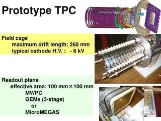
FIRST GEM-TPC PROTOTYPE HB1 – TEST Tests and assembling at Comenius University - Bratislava HV Power Suppliers. TDC module. Source 1D movement controller. Shaper module. Linear Amplifiers. CAMAC create Field cage of 60 mm drift Flange the GEM-TPC HB1 equipped with delayed lines GEM Stack integration First GEM-TPC detector 13
FIRST GEM-TPC PROTOTYPE HB1 – TEST GEM-TPC test in lab at Comenius University GEM-TPC tracking capabilities for 55Fe It can be observed: • Signals from the delayed lines are very clean • Same relative time between them • Trigger signal bipolar, it can be that the 40% negative overshoot is due to e- transparency loses in the GEM 3 In the picture above there are multiple picks from the different source positions. The source was not very well collimated therefore a mm scale resolution on X was achieved and the trigger was taken from the bottom of the GEM3 Trigger Signal with rise and decay time reshaped Trigger Signal before reshaping 14
FIRST GEM-TPC PROTOTYPE HB1 – TEST (cont.) GEM-TPC Beam test at GSI - Darmstadt Beam profile 64Ni ions at 550 MeV/u At the prespec experiment - S363 GEM-TPC Gain GEM-TPC at S4 15
FIRST GEM-TPC PROTOTYPE HB1– TEST (cont.) GEM-TPC Beam test Results GEM-TPC response in X and Y coordinates On the bottom after applying corrections for the preAmps nonlinearities, we can observe that the response is uniform along the full sensitive volume. Resolution in X 400 mm Resolution in Y 300 mm 16
SECOND GEM-TPC PROTOTYPE HB2 The second GEM-TPC HB2 will be tested and characterized in a similar way as for the first one. Test in the lab: • Foils visual and scanned inspection • Foils leakage current measurement • Readout board capacitance measurement • Energy resolution measurement • Gain and its uniformity • Oxygen concentration measurement • Irradiation with 55Fe 17
SECOND GEM-TPC PROTOTYPE HB2 (cont.) The trigger rate expected for the AFTER chip with ArCO2 and 60 mm drift is of about 6.4 kHz. Taken into account that a total of 60 cells are needed and the clock is at 45 MHz GEM-TPC Readout Electronics and DAQ. Readout Architecture T2K FEC developed at TUM 4 AFTER chips for a total of 256 channels 4 x AFTER FEC 2 x ADC to USB Cards Computer PAN to SAMTEC Adapter GEM-TPC Readout board with 1024 strips cut in the middle At the top a Samtec connector 300 pins and in the left side two Panasonic connectors of 130 pins each 18
SECOND GEM-TPC PROTOTYPE HB2 (cont.) GEM-TPC readout electronics performance Calibration Procedure with Test pulses of 50 fC Tpk116 ns Presented by Igor Konorov at TUM Tpk200 ns T2K noise measured @ Saclay Test of One AFTER Chip which is wasn’t connected to the detector and has 8 channels disconnected (the first and the last 4). There is a fixed pattern with 4 noisy channels. Related to the signal amplitude 1 ADC count correspond to 0.12 fC or 700 e- Due to strips and coupled capacitance we can expect a 400 e- noise at all the peaking times 19
THIRD GEM-TPC PROTOTYPE HB3(cont.) GEM-TPC Readout Electronics and DAQ. Presented by Dr. Christian Schmidt at GSI XYTER readout Architecture n-XYTER, non rad hard AMS 0.35µ PEXOR & TRIXOR nXyter Boards #0 #1 Exploder Boards #0 • Detector operation with purely data driven, self triggered readout • engineering run prepared by H.K. Soltveit, PI Heidelberg #1 #2 (Source of 32 MHz) 20
THIRD GEM-TPC PROTOTYPE HB3 (cont.) GEM-TPC Readout Electronics and DAQ. Presented by Dr. Ivan Rusanov at GSI nXYTER readout Architecture nXyter Board 0 Exploder Board 0 Optical Link (fiber) ADC Multi Branch System Lattice FPGA System Clock (copper) Control Block PEXOR and TRIXOR SPI & ADC Triggers (copper) Reset (copper) nXyter I2C & nXyter 128 Detector Optical Link nXyter Board N Exploder Board N • Characteristics: • Slow control via I2C • Max Trigger window of 96 ms • Max Trigger rate 10 kHz (above • trigger window) ADC Lattice FPGA SPI & ADC nXyter I2C & nXyter 128 21
ACTIVE DIVIDER FOR GEM-TPC GEM-TPC Active Divider Presented by Dr. Fabrizio Murtas at INFN One Channel Module With dual current limit: In the low range from 10nA up to 6µA with a resolution of 40 nA And With the high range from 100nA up to 40µA, with a resolution of 40 nA • Main characteristics: • Standard NIM two units. • USB & CAN-OPEN protocol communication interface. • It has 7 independent channels with full isolation at 5kV to Ground. • With 6 channels from 0V to 700V with a max current of 150µA • And • With 1 channel from 0V to 1400V with a max current of 100µA HV GEM module with High Current sensitivity 22
ACTIVE DIVIDER FOR GEM-TPC Test bench in the lab. GEM-TPC Active Divider The interface is very user friendly in order to control Voltages across the GEMs and the fields in between GEMs. In addition to that the current through the GEMs can be monitored 23
OPEN QUESTIONS • Characterization of the GEM foils defects and its uniformity • Field Uniformity mapping for the Field cage with different strips pitch, strips widths and for single and double strips versus different field gradients • Optimization of the Field cage for larger Drift length • Studies on the Ion feedback – simulations and experiment • Calculations of Charge up effects and Gain from simulations • Readout electrode geometry optimizations for different ions types, momenta and count rate • Signal induction for different type of gases based on ArCO2 with CF4 and other gas mixtures. 24
TODO • Finalizing the Second and Third Prototypes. Lab. and beam tests • Integration of the AFTER readout electronics into HB2 and setup of the DAQ • Integration of the Xyter readout electronics into HB3 and setup of the DAQ • Obtain the tracking parameters like: track resolution in X and Y and maximum count rate for HB2 and HB3 • Participate in the Beam campaigns of GPAC at GSI, RD51 at CERN and Jyväskylä • Test the HB2 and HB3 for larger than 60 mm Drift length • Analysis of simulations in order to set clear optimizations • Establish road map for the development of the Full side Prototype 25